Home › DRIVE LINE › DIFFERENTIAL › DIFFERENTIAL SYSTEM

DIFFERENTIAL SYSTEM > INSPECTION

for Preparation Click here


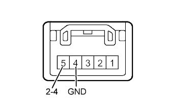
1. INSPECT 4 WHEEL DRIVE CONTROL SWITCH


F044039E02
  1. Using an ohmmeter, measure the resistance between the terminals.
    Switch position
    Tester connection
    Specified condition
    H2
    5 (2-4) - 4 (GND)
    Below 1Ω
    H4
    5 (2-4) → 4 (GND)
    Below 1Ω
    H4
    5 (2-4) ← 4 (GND)
    100 kΩ or higher
    If the result is not as specified, replace the four wheel drive control switch or bulb.


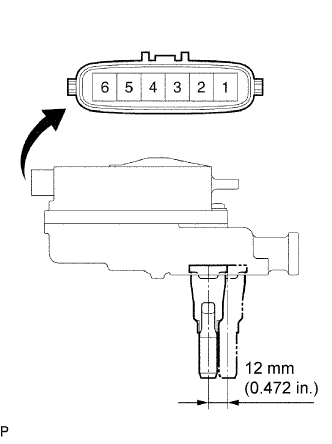
2. INSPECT DIFFERENTIAL VACUUM ACTUATOR ASSEMBLY


F043678E05
  1. Measure the resistance between terminals 1 - 2.

    Standard resistance:
    0.1 to 100 Ω

  1. Measure the resistance between terminals 1 or 2 and the body ground.

    Standard resistance:
    5 MΩ or more

    If the result is not as specified, replace the differential vacuum actuator assembly.

  1. Apply the battery positive voltage between terminals 1 - 2, and check the actuator operation by sound, actuator status and resistance between terminals 3 - 4, 5 - 4 and 6 - 4.

    Battery voltage applied terminal
    3 - 4 terminals resistance
    5 - 4 terminals resistance
    6 - 4 terminals resistance
    Actuator status
    1 (+) - 2 (-)
    Below 1 Ω
    Below 1 Ω
    10 kΩ or higher
    Connected
    1 (-) - 2 (+)
    10 kΩ or higher
    10 kΩ or higher
    Below 1 Ω
    Disconnected


3. INSPECT 4 WHEEL DRIVE CONTROL ECU


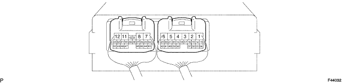
  1. Connect the wire harness side connector to the four wheel drive control ECU and inspect the wire harness side connector from the back side, as shown.


    F044032


    STANDARD VALUE OF ECU TERMINAL 
    Terminals (Symbols)
    Conditions
    STD Voltage (V)
    2 (TM1) - 1 (TM2)
    1. Ignition switch ON
    2. Differential lock switch in OFF position
    3. Four wheel drive control switch H2 position → H4 position
    10 to 14
    1 (TM2) - 2 (TM1)
    1. Ignition switch ON
    2. Keep pressing differential lock switch for approx. 2 seconds to turn it ON
    3. Four wheel drive control switch L4 position → H4 position
    10 to 14
    3 (DM1) - 4 (DM2)
    1. Ignition switch ON
    2. A.D.D. FREE → LOCK
    10 to 14 or 0 to 14 pulse generation then less than 0.5
    4 (DM2) - 3 (DM1)
    1. Ignition switch ON
    2. A.D.D. LOCK → FREE
    10 to 14 or 0 to 14 pulse generation then less than 0.5
    12 (GND) - Body ground
    Ignition switch OFF
    Below 1Ω
    11 (IG) - 12 (GND)
    Ignition switch ON
    10 to 14
    18 (DL2) - 12 (GND)
    1. Ignition switch ON
    2. A.D.D. LOCK → FREE
    1.5 or less → 10 to 14
    19 (DL1) - 12 (GND)
    1. Ignition switch ON
    2. A.D.D. FREE → LOCK
    1.5 or less → 10 to 14
    25 (2-4) - 12 (GND)
    1. Ignition switch ON
    2. Four wheel drive control switch L4 position → H2 position or H4 position
    10 to 14 → 1.5 or less
    26 (SPD) - 12 (GND)
    During driving
    Pulse generation
    28 (IND3) - 12 (GND)
    1. Ignition switch ON
    2. Four wheel drive control switch H4 position → L4 position
    10 to 14 → 1.5 to 3.5
    32 (LO) - 12 (GND)
    1. Ignition switch ON
    2. Four wheel drive control switch H4 position → L4 position
    10 to 14 → 1.5 or less
    42 (ADD) - 12 (GND)
    1. Ignition switch ON
    2. A.D.D. FREE → LOCK
    10 to 14 → 1.5 or less
    23 (L4) - 12 (GND)
    1. Ignition switch ON
    2. Four wheel drive control switch H2 position or H4 position → L4 position
    10 to 14 → 1.5 or less
    38 (4WD) - 12 (GND)
    1. Ignition switch ON
    2. Four wheel drive control switch H2 position → H4 position
    10 to 14 → 1.5 or less
    39 (TL3) - 12 (GND)
    1. Ignition switch ON
    2. Four wheel drive control switch H2 position → L4 position
    10 to 14 → 0.88 or less
    40 (TL2) - 12 (GND)
    1. Ignition switch ON
    2. Four wheel drive control switch H2 position → H4 position
    10 to 14 → 0.88 or less
    41 (TL1) - 12 (GND)
    1. Ignition switch ON
    2. Four wheel drive control switch H2 position → H4 position or L4 position
    0.88 or less → 10 to 14
    45 (IND1) - 12 (GND)
    1. Ignition switch ON
    2. Four wheel drive control switch H2 position → H4 position or L4 position
    10 to 14 → 0 to 3.5
    48 (N) - 12 (GND)
    1. Ignition switch ON
    2. Transmission shift lever other position → N position
    1.5 or less → 10 to 14
    49 (MTN) - 12 (GND)
    1. Ignition switch ON
    2. Clutch start switch OFF position → ON position
    10 to 14 → 1.5 or less


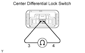
4. INSPECT CENTER DIFFERENTIAL LOCK SWITCH (w/ Differential Lock)


    F051298E02
  1. Check the resistance.

    1. Measure the resistance using an ohmmeter.

      Standard:
      Tester Connection
      Switch Condition
      Specified Condition
      3 - 4
      Released
      10 kΩ or higher
      Pushed in
      Below 1 Ω

      If the result is not as specified, replace the center differential lock switch.


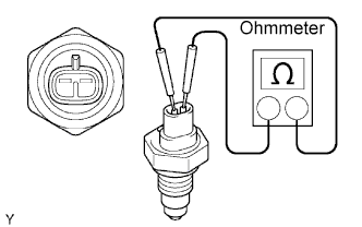
5. INSPECT NO. 1 TRANSFER INDICATOR SWITCH (w/ Differential Lock)


    F051400E02
  1. Check the resistance.

    1. Measure the resistance using an ohmmeter.

      Standard:
      Tester Connection
      Switch Condition
      Specified Condition
      1 - 2
      Released
      10 kΩ or higher
      Pushed in
      Below 1 Ω

      If the result is not as specified, replace the No. 1 transfer indicator switch.