DIFFERENTIAL CARRIER ASSEMBLY (w/o Differential Lock) > REASSEMBLY |
| 1. ASSEMBLE DIFFERENTIAL CASE ASSEMBLY |
|
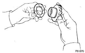
Install the 2 side gear thrust washers to the side gears.
Install the 2 side gears with the side gear thrust washers, 2 pinion gears, 2 pinion gear thrust washers and the pinion shaft.
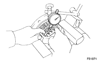 |
Using a dial indicator, measure the side gear backlash while holding one pinion gear toward the differential case.
| Part No. | Thickness mm (in.) |
| 41361-34010 | 1.50 (0.0590) |
| 41361-34020 | 1.55 (0.0610) |
| 41361-34030 | 1.60 (0.0630) |
| 41361-34040 | 1.65 (0.0650) |
| 41361-34050 | 1.70 (0.0669) |
| 41361-34060 | 1.75 (0.0689) |
| 41361-34070 | 1.80 (0.0709) |
| 41361-34080 | 1.85 (0.0728) |
| 41361-34090 | 1.90 (0.0748) |
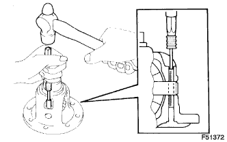 |
Using a pin punch and hammer, install the straight pin through the holes in the differential case assembly and the pinion shaft.
Using a chisel and hammer, stake the outside of the differential case pin hole.
| 2. INSTALL DIFFERENTIAL RING GEAR |
 |
Clean the contact surfaces of the differential case assembly and the differential ring gear.
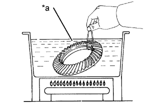
Heat the differential ring gear to approximately 100°C (212°F) in boiling water.
| *a | Boiling Water |
Carefully take the differential ring gear out of the boiling water.
After the moisture on the differential ring gear has completely evaporated, quickly install the differential ring gear onto the differential case assembly.
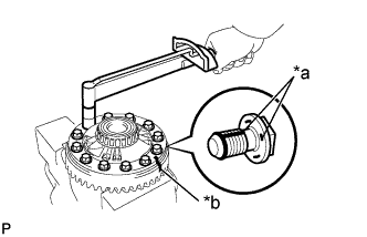 |
After the differential ring gear has cooled sufficiently, apply adhesive to the 12 bolts.
| *a | Adhesive |
| *b | Matchmark |
Install the 12 bolts.
| 3. INSTALL REAR DIFFERENTIAL CASE BEARING |
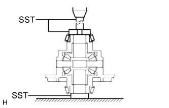 |
Using SST and a press, install the 2 side bearings into the differential case.
| 4. INSPECT DIFFERENTIAL RING GEAR RUNOUT |
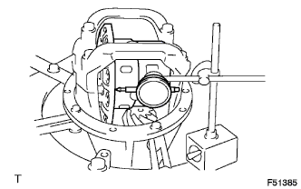 |
Install the differential case assembly to the rear differential carrier, and install the 2 plate washers so that there is no play in the bearing.
Install the differential bearing cap with the 4 bolts.
Using a dial indicator, measure the runout of the differential ring gear.
Remove the differential bearing cap, 2 plate washers and the differential case assembly.
| 5. INSTALL REAR DIFFERENTIAL DUST DEFLECTOR |
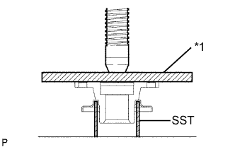 |
Using a press, install the rear differential dust deflector.
| *1 | Plate |
| 6. INSTALL REAR DRIVE PINION FRONT TAPERED ROLLER BEARING |
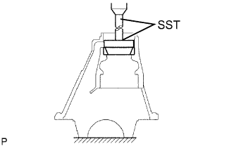 |
Using SST and a press, install the rear drive pinion front tapered roller bearing onto the rear differential carrier assembly.
| 7. INSTALL REAR DRIVE PINION REAR TAPERED ROLLER BEARING |
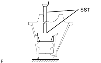 |
Install the rear differential drive pinion plate washer to the rear differential carrier assembly.
Using SST and a press, install the rear drive pinion rear tapered roller bearing to the rear differential carrier assembly.
| 8. INSTALL REAR DRIVE PINION REAR TAPERED ROLLER BEARING |
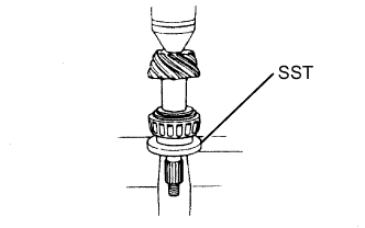 |
Using SST and a press, install the rear drive pinion rear tapered roller bearing to the differential drive pinion.
| 9. ADJUST DIFFERENTIAL DRIVE PINION PRELOAD |
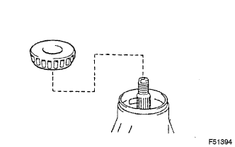 |
Install the differential drive pinion and the rear drive pinion front tapered roller bearing.
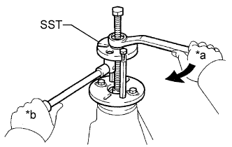 |
Using SST, install the rear drive pinion companion flange sub-assembly.
Coat the threads of the nut with hypoid gear oil LSD.
| *a | Turn |
| *b | Hold |
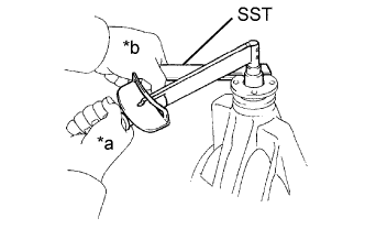 |
Using SST to hold the rear drive pinion companion flange sub-assembly, tighten the rear drive pinion nut.
| *a | Turn |
| *b | Hold |
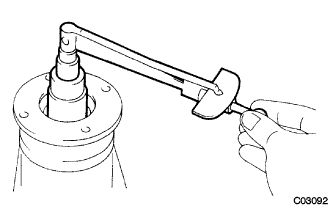 |
Using a torque wrench, measure the preload.
| Item | Specified Condition |
| New bearing | 1.27 to 1.86 N*m (13 to 20 kgf*cm, 11 to 16 in.*lbf) |
| Used bearing | 0.78 to 1.07 N*m (8.0 to 11 kgf*cm, 6.9 to 9.5 in.*lbf) |
| 10. INSTALL DIFFERENTIAL CASE ASSEMBLY |
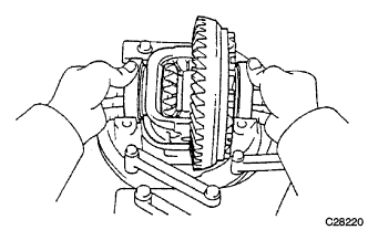 |
Place the 2 bearing outer races on their corresponding bearings.
Install the differential case assembly into the rear differential carrier assembly.
| 11. ADJUST DIFFERENTIAL RING GEAR BACKLASH |
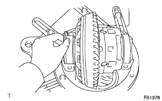 |
Install the plate washer to the ring gear back side.
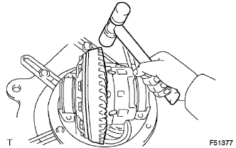 |
Tap on the differential ring gear with a plastic-faced hammer so that the washer fits into the bearing.
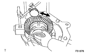 |
Using a dial indicator, measure the differential ring gear backlash while holding the rear drive pinion companion flange.
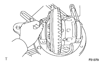 |
Select a plate washer for the back side ring gear using the backlash as a reference.
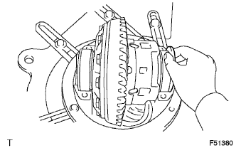 |
Select a ring gear teeth side plate washer so that there is no clearance between the outer race and the case.
Remove the 2 plate washers and differential case.
Install the plate washer into the ring gear back side of the carrier.
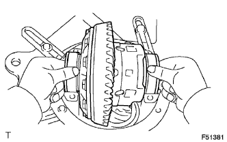 |
Place the other plate washer to the differential case assembly together with the outer race, and install the differential case assembly with the outer race into the carrier.
Tap on the ring gear with a plastic-faced hammer so that the washers fit into the bearing.
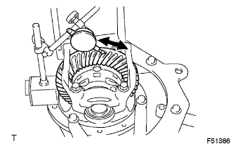 |
Using a dial indicator, measure the ring gear backlash while holding the rear drive pinion companion flange.
| 12. ADJUST SIDE BEARING PRELOAD |
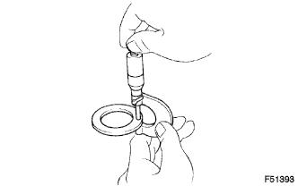 |
Remove the ring gear teeth side plate washer and using a micrometer, measure the thickness.
Using the backlash as a reference, install a new washer 0.06 to 0.09 mm (0.00236 to 0.00354 in.) thicker than the removed one.
Using a plastic-faced hammer, install the plate washer.
|
Recheck the ring gear backlash.
| Part No. | Mark | Thickness mm (in.) | Part No. | Mark | Thickness mm (in.) |
| 90201-70064 | 58 | 2.58 (0.1016) | 90201-70087 | 04 | 3.04 (0.1197) |
| 90201-70065 | 60 | 2.60 (0.1024) | 90201-70088 | 06 | 3.06 (0.1205) |
| 90201-70066 | 62 | 2.62 (0.1032) | 90201-70089 | 08 | 3.08 (0.1213) |
| 90201-70067 | 64 | 2.64 (0.1039) | 90201-70090 | 10 | 3.10 (0.1221) |
| 90201-70068 | 66 | 2.66 (0.1047) | 90201-70091 | 12 | 3.12 (0.1228) |
| 90201-70069 | 68 | 2.68 (0.1055) | 90201-70092 | 14 | 3.14 (0.1236) |
| 90201-70070 | 70 | 2.70 (0.1063) | 90201-70093 | 16 | 3.16 (0.1244) |
| 90201-70071 | 72 | 2.72 (0.1071) | 90201-70094 | 18 | 3.18 (0.1257) |
| 90201-70072 | 74 | 2.74 (0.1079) | 90201-70095 | 20 | 3.20 (0.1260) |
| 90201-70073 | 76 | 2.76 (0.1087) | 90201-70096 | 22 | 3.22 (0.1268) |
| 90201-70074 | 78 | 2.78 (0.1095) | 90201-70097 | 24 | 3.24 (0.1276) |
| 90201-70075 | 80 | 2.80 (0.1102) | 90201-70098 | 26 | 3.26 (0.1284) |
| 90201-70076 | 82 | 2.82 (0.1110) | 90201-70099 | 28 | 3.28 (0.1291) |
| 90201-70077 | 84 | 2.84 (0.1118) | 90201-70100 | 30 | 3.30 (0.1299) |
| 90201-70078 | 86 | 2.86 (0.1126) | 90201-70101 | 32 | 3.32 (0.1307) |
| 90201-70079 | 88 | 2.88 (0.1134) | 90201-70102 | 34 | 3.34 (0.1315) |
| 90201-70080 | 90 | 2.90 (0.1142) | 90201-70103 | 36 | 3.36 (0.1323) |
| 90201-70081 | 92 | 2.92 (0.1150) | 90201-70104 | 38 | 3.38 (0.1331) |
| 90201-70082 | 94 | 2.94 (0.1158) | 90201-70105 | 40 | 3.40 (0.1339) |
| 90201-70083 | 96 | 2.96 (0.1165) | 90201-70106 | 42 | 3.42 (0.1347) |
| 90201-70084 | 98 | 2.98 (0.1173) | 90201-70107 | 44 | 3.44 (0.1354) |
| 90201-70085 | 00 | 3.00 (0.1181) | 90201-70108 | 46 | 3.46 (0.1362) |
| 90201-70086 | 02 | 3.02 (0.1189) | 90201-70109 | 48 | 3.48 (0.1370) |
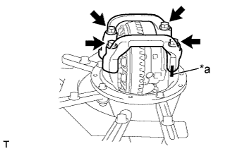 |
Align the matchmarks on the cap and the carrier.
| *a | Matchmarks |
Install the cap with the 4 bolts.
| 13. INSPECT TOTAL PRELOAD |
|
Using a torque wrench, measure the preload with the teeth of the differential drive pinion and differential ring gear in contact.
| 14. INSPECT TOOTH CONTACT BETWEEN RING GEAR AND DRIVE PINION |
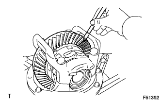 |
Coat 3 or 4 teeth at 3 different positions on the differential ring gear with Prussian blue.
Hold the companion flange firmly and rotate the differential ring gear in both directions.
Inspect the tooth contact pattern.
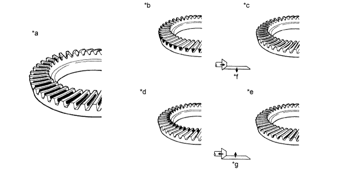
| *a | Proper Contact | *b | Heel Contact |
| *c | Face Contact | *d | Toe Contact |
| *e | Flank Contact | *f | Select an adjusting washer that bring the drive pinion closer to the ring gear |
| *g | Select an adjusting washer that shift the drive pinion away from the ring gear | - | - |
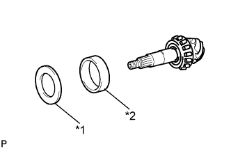 |
If the teeth are not properly in contact, use the following chart to select an appropriate washer for correction.
| *1 | Rear Differential Drive Pinion Plate Washer |
| *2 | Rear Drive Pinion Rear Tapered Roller Bearing (Outer) |
| Part No. | Mark | Thickness mm (in.) | Part No. | Mark | Thickness mm (in.) |
| 90201-70002 | 88 | 1.88 (0.0740) | 90201-70024 | 10 | 2.10 (0.0827) |
| 90201-70004 | 90 | 1.90 (0.0748) | 90201-70026 | 12 | 2.12 (0.0835) |
| 90201-70006 | 92 | 1.92 (0.0756) | 90201-70028 | 14 | 2.14 (0.0843) |
| 90201-70008 | 94 | 1.94 (0.0764) | 90201-70030 | 16 | 2.16 (0.0850) |
| 90201-70010 | 96 | 1.96 (0.0772) | 90201-70032 | 18 | 2.18 (0.0858) |
| 90201-70012 | 98 | 1.98 (0.0780) | 90201-70034 | 20 | 2.20 (0.0866) |
| 90201-70014 | 00 | 2.00 (0.0787) | 90201-70036 | 22 | 2.22 (0.0874) |
| 90201-70016 | 02 | 2.02 (0.0795) | 90201-70038 | 24 | 2.24 (0.0882) |
| 90201-70018 | 04 | 2.04 (0.0803) | 90201-70040 | 26 | 2.26 (0.0890) |
| 90201-70020 | 06 | 2.06 (0.0811) | 90201-70042 | 28 | 2.28 (0.0898) |
| 90201-70022 | 08 | 2.08 (0.0819) | 90201-70044 | - | - |
| 15. REMOVE REAR DRIVE PINION NUT |
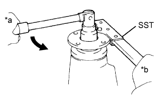 |
Using SST to hold the differential drive pinion companion flange sub-assembly, remove the nut.
| *a | Turn |
| *b | Hold |
| 16. REMOVE REAR DRIVE PINION COMPANION FLANGE SUB-ASSEMBLY |
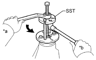 |
Using SST, remove the rear drive pinion companion flange sub-assembly.
| *a | Turn |
| *b | Hold |
| 17. REMOVE REAR DRIVE PINION FRONT TAPERED ROLLER BEARING |
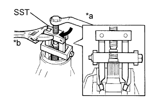 |
Using SST, remove the rear drive pinion tapered roller bearing from the differential drive pinion.
| *a | Turn |
| *b | Hold |
| 18. INSTALL REAR DIFFERENTIAL DRIVE PINION BEARING SPACER |
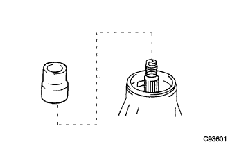 |
Install a new rear differential drive pinion bearing spacer onto the differential drive pinion.
| 19. INSTALL REAR DRIVE PINION FRONT TAPERED ROLLER BEARING |
|
| 20. INSTALL REAR DIFFERENTIAL CARRIER OIL SEAL |
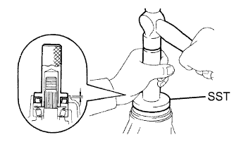 |
Apply MP grease to the oil seal lip.
Using SST and a hammer, install a new rear differential carrier oil seal.
| 21. INSTALL REAR DRIVE PINION COMPANION FLANGE SUB-ASSEMBLY |
|
Using SST, install the rear drive pinion companion flange sub-assembly to the differential drive pinion.
| *a | Turn |
| *b | Hold |
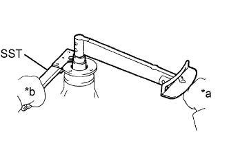 |
Coat the threads of a new nut with hypoid gear oil LSD.
Using SST to hold the rear drive pinion companion flange, tighten the nut.
| *a | Turn |
| *b | Hold |
| 22. INSPECT DRIVE PINION PRELOAD |
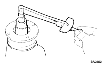 |
Using a torque wrench, measure the preload of the backlash between the differential drive pinion and the differential ring gear.
| Item | Specified Condition |
| New bearing | 1.27 to 1.86 N*m (13 to 19 kgf*cm, 11 to 16 in.*lbf) |
| Used bearing | 0.78 to 1.07 N*m (8.0 to 11 kgf*cm, 6.9 to 9.5 in.*lbf) |
| 23. INSPECT TOTAL PRELOAD |
|
Using a torque wrench, measure the preload.
| 24. INSPECT DIFFERENTIAL RING GEAR BACKLASH |
|
Using a dial indicator, check the backlash of the differential ring gear.
| 25. INSPECT RUNOUT OF REAR DRIVE PINION COMPANION FLANGE SUB-ASSEMBLY |
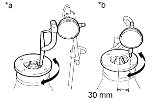 |
Using a dial indicator, measure the vertical and lateral runout of the rear drive pinion companion flange sub-assembly.
| *a | Vertical Runout |
| *b | Lateral Runout |
| Item | Specified Condition |
| Vertical runout | 0.09 mm (0.00354 in.) |
| Lateral runout | 0.09 mm (0.00354 in.) |
| 26. INSTALL REAR DRIVE PINION NUT |
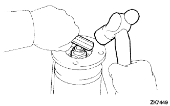 |
Using a chisel and hammer, stake the nut.