 |
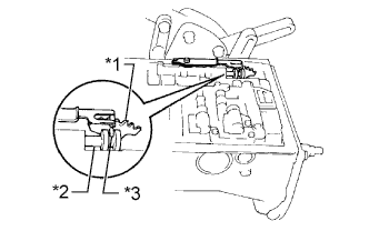
Align the groove of the manual valve with the pin of the lever.
| *1 | Manual Valve Lever |
| *2 | Manual Valve |
| *3 | Pin |
VALVE BODY ASSEMBLY > INSTALLATION |
| 1. INSTALL TRANSMISSION VALVE BODY ASSEMBLY |
Coat 2 new O-rings with ATF and install them to the shift solenoid valves S1 and S2.
Install the shift solenoid valves S1 and S2 with the bolt.
Install the shift solenoid valve SLT with the bolt.
Install the shift solenoid valve SLU with the bolt.
|
Align the groove of the manual valve with the pin of the lever.
| *1 | Manual Valve Lever |
| *2 | Manual Valve |
| *3 | Pin |
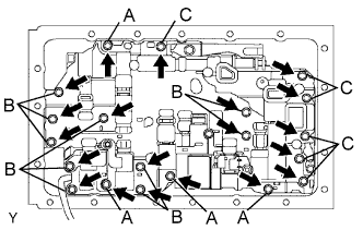 |
Install the 20 bolts.
| 2. INSTALL TRANSMISSION WIRE |
Coat a new O-ring with Toyota Genuine ATF Type T-IV or equivalent, and install it onto the transmission wire.
Install the transmission wire onto the case, and install the stopper plate.
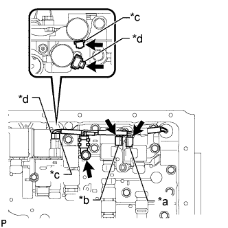 |
Connect the connectors to each shift solenoid valve.
| *a | White |
| *b | Black |
| *c | Orange/Green |
| *d | Yellow/Brown |
Connect the temperature sensor with temperature sensor clamp and the bolt.
| 3. INSTALL VALVE BODY OIL STRAINER ASSEMBLY |
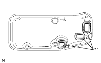 |
Install 3 new gaskets.
| *1 | Gasket |
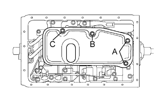 |
Install the oil strainer with the 4 bolts.
| 4. INSTALL AUTOMATIC TRANSMISSION OIL PAN SUB-ASSEMBLY |
Remove any packing material and be careful not to drop oil on the contact surfaces of the transmission case and oil pan sub-assembly.
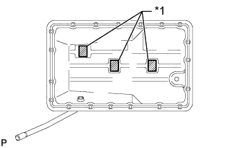 |
Install the 3 magnets onto the oil pan sub-assembly, in the portions indicated in the illustration.
| *1 | Magnet |
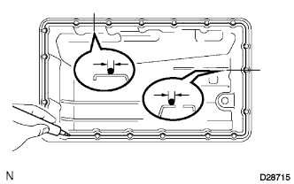 |
Apply seal packing to the oil pan as shown in the illustration.
Install the oil pan sub-assembly with the 19 bolts.
| 5. INSTALL TRANSMISSION OIL FILLER TUBE SUB-ASSEMBLY |
Coat a new O-ring with Toyota Genuine ATF Type T-IV or equivalent and install it onto the oil filler tube.
Install the oil filler tube with the 2 bolts.
| 6. ADD AUTOMATIC TRANSMISSION FLUID |
| 7. INSPECT AUTOMATIC TRANSMISSION FLUID |
Park the vehicle on a level surface and set the parking brake.
With the engine idling and the brake pedal depressed, move the shift lever into all positions from P to L. Then return it to P.
Pull out the dipstick and wipe it clean.
Push it back fully into the pipe.
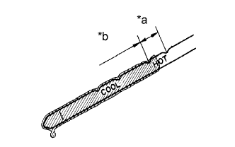 |
Pull it out and check that the fluid level is in the HOT range.
| *a | OK |
| *b | Add |
| 8. INSPECT FOR AUTOMATIC TRANSMISSION FLUID LEAK |