COMPRESSOR > INSTALLATION |
| 1. ADJUST COMPRESSOR OIL |
When replacing the compressor and magnetic clutch with new ones, after gradually discharging the refrigerant gas from the service valve, drain the following volume of oil from new compressor and magnetic clutch before installation.
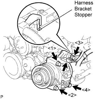
| 2. INSTALL COMPRESSOR AND MAGNETIC CLUTCH (for 2TR-FE) |
|
Provisionally tighten the compressor and magnetic clutch with the 4 bolts and harness bracket.
Tighten the compressor and magnetic clutch with the 4 bolts.
Connect the connector.
| 3. INSTALL COMPRESSOR AND MAGNETIC CLUTCH (for 1GR-FE) |
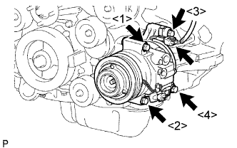 |
Provisionally tighten the compressor and magnetic clutch with the 4 bolts.
Tighten the compressor and magnetic clutch with the 4 bolts.
Connect the connector.
| 4. INSTALL DISCHARGE HOSE SUB-ASSEMBLY |
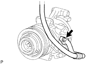 |
Remove the attached vinyl tape from the hose.
Apply sufficient compressor oil to a new seal washer and fitting surface of the compressor and magnetic clutch.
Install the seal washer onto the cooler refrigerant discharge hose sub-assembly.
Install the cooler refrigerant discharge hose sub-assembly onto the compressor and magnetic clutch with the bolt.
| 5. INSTALL SUCTION HOSE SUB-ASSEMBLY (for 2TR-FE) |
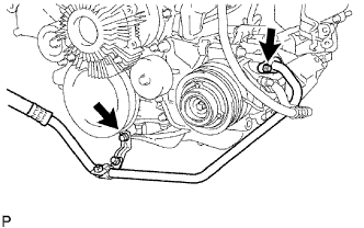 |
Remove the attached vinyl tape from the hose.
Apply sufficient compressor oil to a new seal washer and fitting surface of the compressor and magnetic clutch.
Install the seal washer onto the suction hose sub-assembly.
Install the suction hose sub-assembly onto the compressor and magnetic clutch with the bolt.
Install the suction hose sub-assembly with the bolt.
| 6. INSTALL SUCTION HOSE SUB-ASSEMBLY (for 1GR-FE) |
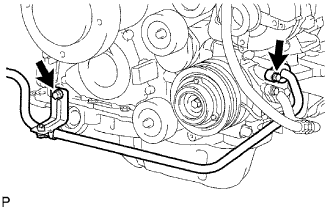 |
Remove the attached vinyl tape from the hose.
Apply sufficient compressor oil to a new seal washer and fitting surface of the compressor and magnetic clutch.
Install the seal washer onto the suction hose sub-assembly.
Install the suction hose sub-assembly onto the compressor and magnetic clutch with the bolt.
Install the suction hose sub-assembly with the bolt.
| 7. INSTALL FRONT FENDER APRON SEAL UPPER |
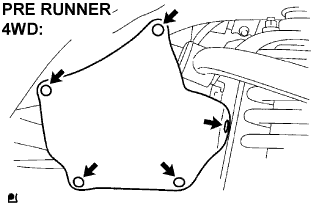 |
Install the front fender apron seal upper with the 5 clips. (4WD, PRE RUNNER)
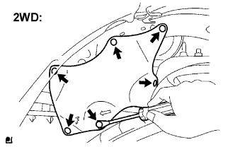 |
Install the front fender apron seal upper with the 6 clips. (2WD)
| 8. INSTALL GENERATOR ASSEMBLY (for 1GR-FE) |
Install the generator assembly with the 2 bolts.
Install the wire harness clamp bracket with the 2 bolts.
Connect the wire harness.
Connect the wire harness to terminal B and install the nut.
Connect the connector to the generator assembly.
Install the wire harness stay with the bolt.
| 9. INSTALL FAN & GENERATOR V BELT (for 2TR-FE) |
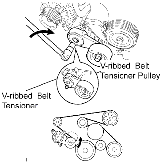 |
Provisionally install the V belt onto each pulley.
Turn the hexagonal bolt on the V-ribbed belt tensioner clockwise and install the V belt onto the V-ribbed belt tensioner pulley.
| 10. INSPECT FAN & GENERATOR V BELT (for 2TR-FE) |
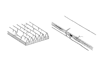 |
Visually check the belt for excessive wear, frayed cords, etc..
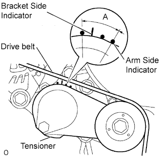 |
Check that the tensioner indicator mark is within range A shown in the illustration. If the mark is not within range A, replace the V belt.
| 11. INSTALL FAN & GENERATOR V BELT (for 1GR-FE) |
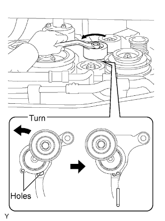 |
While turning the belt tensioner counterclockwise, align with its holes, and then insert a bar of 6 mm (0.24 in.) into the holes to fix the belt tensioner.
Install the V-ribbed belt.
While turning the belt tensioner counterclockwise, remove the bar.
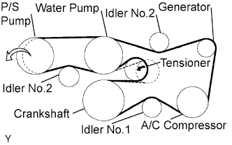 |
If it is hard to install the V-ribbed belt, perform the following procedure.
Put the V-ribbed belt on all parts except the P/S pump, as shown in the illustration.
While releasing the belt tension by turning the belt tensioner counterclockwise, put the V-ribbed belt on the P/S pump.
| 12. INSTALL FAN SHROUD (for 1GR-FE) |
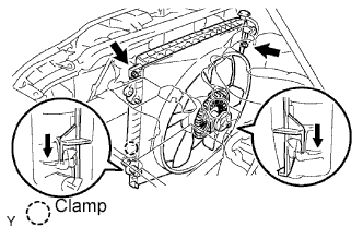 |
Provisionally install the fan shroud together with the fan pulley.
Install the fan and generator V belt .
Install the fan pulley with the 4 nuts.
Install the fan shroud with the 2 bolts.
Install the 2 cooler hoses into the clamp (with automatic transmission).
Connect the hose to the radiator reserve tank.
| 13. INSTALL RADIATOR SUPPORT TO FRAME SEAL LH (for 1GR-FE) |
| 14. INSTALL V-BANK COVER (for 1GR-FE) |
Install the V-bank cover with the 2 nuts.
| 15. INSTALL NO. 1 ENGINE UNDER COVER SUB-ASSEMBLY (for 2TR-FE) |
Install the engine under cover No. 1 with the 4 bolts.
| 16. INSTALL NO. 1 ENGINE UNDER COVER SUB-ASSEMBLY (for 1GR-FE) |
Install the engine under cover with the 4 bolts.
| 17. INSTALL FRONT WHEEL LH |
| 18. CONNECT CABLE TO NEGATIVE BATTERY TERMINAL |
| 19. CHARGE REFRIGERANT |
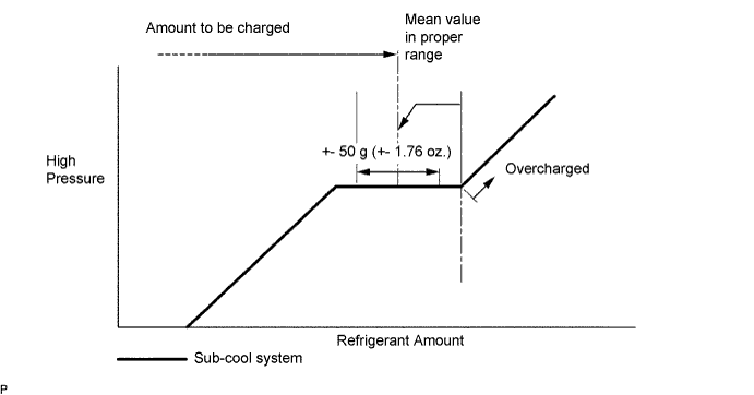
Perform vacuum purging using a vacuum pump.
Charge refrigerant HFC-134a (R134a).
| 20. WARM UP ENGINE |
| 21. CHECK FOR REFRIGERANT LEAK |
After recharging the refrigerant gas, check for refrigerant gas leakage using a halogen leak detector.
Perform the operation under these conditions:
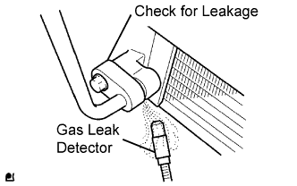 |
Using a gas leak detector, check the refrigerant line for leakage.
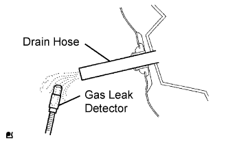 |
Bring the gas leak detector close to the drain hose with the detector power off.
If a gas leak is not detected from the drain hose, remove the blower motor control from the cooling unit. Insert the gas leak detector sensor into the unit and perform the test.
Disconnect the pressure switch connector and leave it for approximately 20 minutes. Bring the gas leak detector close to the pressure switch and perform the test.