 |
Connect the hood lock control cable assembly.
POWER OUTLET SOCKET > INSTALLATION |
| 1. INSTALL POWER POINT SOCKET ASSEMBLY |
Align the socket with the notch on the power point socket cover, and push the power point socket assembly firmly into the cover to install it.
| 2. INSTALL INSTRUMENT LOWER COVER SUB-ASSEMBLY |
Connect the connectors.
Engage the 5 clips and install the instrument lower cover.
Install the bolt <B>.
| 3. INSTALL LOWER INSTRUMENT PANEL LH |
Install the lower instrument panel LH with the 3 bolts <B>.
| 4. INSTALL INSTRUMENT CLUSTER CENTER FINISH PANEL SUB-ASSEMBLY |
Engage the 10 clips and install the instrument cluster center finish panel sub-assembly.
| 5. INSTALL INSTRUMENT CLUSTER FINISH PANEL SUB-ASSEMBLY |
Connect the connectors.
Engage the 6 clips and install the instrument cluster finish panel sub-assembly.
Install the 2 clips.
| 6. INSTALL LOWER NO. 1 INSTRUMENT PANEL FINISH PANEL |
Connect the connectors.
Engage the 3 clips and install the lower NO. 1 instrument panel finish panel sub-assembly.
Install the 2 bolts <B>.
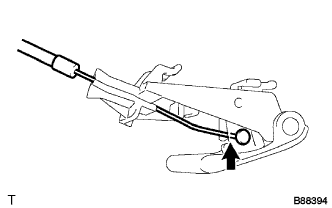
| 7. INSTALL HOOD LOCK CONTROL LEVER SUB-ASSEMBLY |
|
Connect the hood lock control cable assembly.
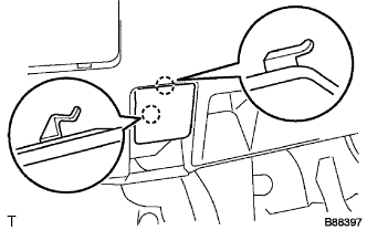 |
Engage the 2 claws and install the hood lock control lever sub-assembly.
| 8. INSTALL RADIO RECEIVER ASSEMBLY |
Connect all the connectors.
Connect the plug.
Engage the 5 clips and install the radio receiver assembly with bracket.
Install the 4 bolts.
| 9. INSTALL RADIO AND DISPLAY RECEIVER ASSEMBLY |
Connect all the connectors.
Engage the 5 clips and install the radio and display receiver assembly with bracket.
Install the 4 bolts.
| 10. INSTALL AIR CONDITIONING CONTROL ASSEMBLY |
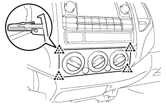 |
Connect the 2 connectors.
Engage the 4 clips and install the air conditioning control assembly.
| 11. INSTALL FRONT CONSOLE BOX (for Manual Transmission on Bench Seat Type) |
Engage the 2 clips and claw, and install the front console box.
Install the clip and 2 bolts <A>.
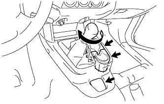 |
Install the 2 instrument panel cup holders.
Install the box bottom mat.
Install the shift knob.
| 12. INSTALL FRONT CONSOLE BOX (for Automatic Transmission on Bench Seat Type) |
Engage the 2 clips and claw, and install the front console box.
Install the clip and 2 bolts <A>.
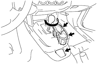 |
Install the 2 instrument panel cup holders.
Install the box bottom mat.
Install the shift knob.
| 13. INSTALL FRONT CONSOLE BOX (for Manual Transmission on Separate Seat Type) |
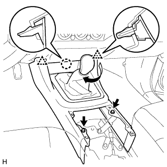 |
Engage the 2 clips and claw, and install the front console box.
Install the 2 screws <F>.
Install the shift knob.
| 14. INSTALL FRONT CONSOLE BOX (for Automatic Transmission on Separate Seat Type) |
Engage the 2 clips and claw, and install the front console box.
Install the 2 screws <F>.
| 15. INSTALL INSTRUMENT PANEL CUP HOLDER TRAY (for Automatic Transmission on Separate Seat Type) |
Engage the 2 clips and 4 claws, and install the instrument panel cup holder tray.
Install the 2 instrument panel cup holders.
| 16. INSTALL REAR CONSOLE BOX ASSEMBLY (for Separate Seat Type) |
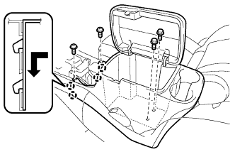 |
Engage the 4 claws and install the console box rear.
Install the 2 screws <F> and 2 bolts <B>.
Install the console box carpet.
| 17. INSTALL CONSOLE UPPER REAR PANEL SUB-ASSEMBLY (for Manual Transmission on Separate Seat Type) |
Engage the 4 clips and claw, and install the console upper panel sub-assembly.
| 18. INSTALL CONSOLE UPPER REAR PANEL SUB-ASSEMBLY (for Automatic Transmission on Separate Seat Type) |
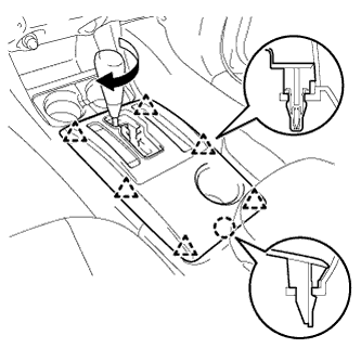 |
Engage the 6 clips and claw, and install the console upper rear panel.
Install the shift knob.
| 19. INSTALL INSTRUMENT PANEL HOLE COVER (for Lever Type Parking Brake) |
Engage the 4 clips and install the instrument panel hole cover.
| 20. INSTALL INSTRUMENT PANEL UNDER TRAY (for Pedal Type Parking Brake) |
Engage the 4 clips and 2 claws, and install the instrument panel under tray.
| 21. INSTALL COWL SIDE TRIM BOARD LH (for Regular Cab) |
Engage the 2 clips and install the cowl side trim board.
Install the clip.
| 22. INSTALL COWL SIDE TRIM BOARD LH (for Access Cab) |
Engage the 2 clips and install the cowl side trim board.
Install the clip.
| 23. INSTALL COWL SIDE TRIM BOARD LH (for Double Cab) |
Engage the 2 clips and install the cowl side trim board.
Install the clip.
| 24. INSTALL FRONT DOOR SCUFF PLATE LH (for Regular Cab) |
Engage the 8 claws and clip, and install the front door scuff plate.
| 25. INSTALL FRONT DOOR SCUFF PLATE LH (for Access Cab) |
Engage the 9 claws and clip, and install the front door scuff plate.
| 26. INSTALL FRONT DOOR SCUFF PLATE LH (for Double Cab) |
Engage the 9 claws and install the front door scuff plate.
| 27. INSTALL FRONT FLOOR FOOTREST |
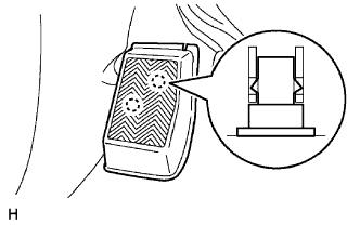 |
Engage the 2 clips and install the front floor footrest.