 |
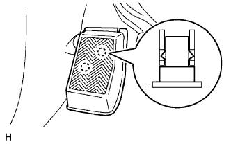
Disengage the 2 clips and remove the front floor footrest.
RADIO ANTENNA CORD > REMOVAL |
| 1. DISCONNECT CABLE FROM NEGATIVE BATTERY TERMINAL |
| 2. REMOVE FRONT FLOOR FOOTREST |
|
Disengage the 2 clips and remove the front floor footrest.
| 3. REMOVE FRONT DOOR SCUFF PLATE LH |
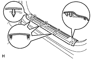 |
Disengage the 9 claws and remove the front door scuff plate.
| 4. REMOVE FRONT DOOR SCUFF PLATE RH |
| 5. REMOVE COWL SIDE TRIM BOARD LH |
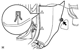 |
Remove the clip.
Disengage the 2 clips and remove the cowl side trim board.
| 6. REMOVE COWL SIDE TRIM BOARD RH |
| 7. SEPARATE FRONT DOOR OPENING TRIM WEATHERSTRIP LH |
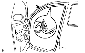 |
Remove the front door opening trim weatherstrip.
| 8. SEPARATE FRONT DOOR OPENING TRIM WEATHERSTRIP RH |
| 9. REMOVE FRONT PILLAR GARNISH LH |
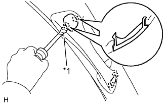 |
Using a screwdriver with its tip taped in protective tape, disengage the 2 claws and remove the assist grip plug.
| *1 | Protective Tape |
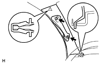 |
Remove the 2 screws.
Disengage the clip and claw and remove the front pillar garnish.
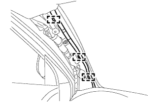 |
for LH side:
Using a clip remover, remove the 3 wire harness clamps.
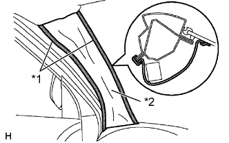 |
w/ Curtain Shield Airbag:
| *1 | Adhesive Tape |
| *2 | Cloth or Nylon |
Thoroughly cover the airbag with cloth or nylon of 700 mm (27.56 in.) x 120 mm (4.72 in.) and fix the ends of the cover with adhesive tape, as shown in the illustration.
| 10. REMOVE FRONT PILLAR GARNISH RH |
| 11. REMOVE INSTRUMENT PANEL UNDER TRAY (for Pedal Type Parking Brake) |
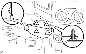 |
Disengage the 4 clips and 2 claws, and remove the instrument panel under tray.
| 12. REMOVE INSTRUMENT PANEL HOLE COVER (for Lever Type Parking Brake) |
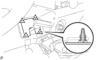 |
Disengage the 4 clips and remove the instrument panel hole cover.
| 13. REMOVE CONSOLE UPPER REAR PANEL SUB-ASSEMBLY (for Automatic Transmission on Separate Seat Type) |
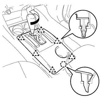 |
Remove the shift knob.
Disengage the 6 clips and claw, and remove the console upper rear panel sub-assembly.
| 14. REMOVE CONSOLE UPPER REAR PANEL SUB-ASSEMBLY (for Manual Transmission on Separate Seat Type) |
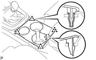 |
Disengage the 4 clips and claw, and remove the console upper rear panel sub-assembly.
| 15. REMOVE REAR CONSOLE BOX ASSEMBLY (for Separate Seat Type) |
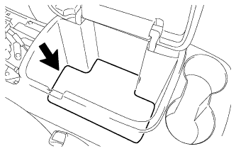 |
Remove the console box carpet.
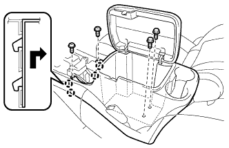 |
Remove the 2 screws <F> and 2 bolts <B>.
Disengage the 4 claws and remove the rear console box assembly.
| 16. REMOVE INSTRUMENT PANEL CUP HOLDER TRAY (for Automatic Transmission on Separate Seat Type) |
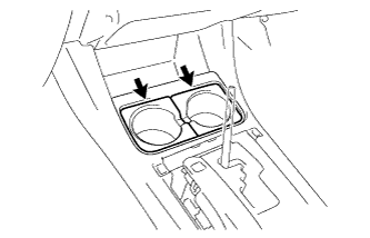 |
Remove the 2 instrument panel cup holders.
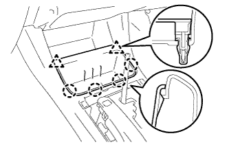 |
Disengage the 2 clips and 4 claws, and remove the instrument panel cup holder tray.
| 17. REMOVE FRONT CONSOLE BOX (for Automatic Transmission on Separate Seat Type) |
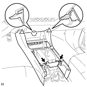 |
Remove the 2 screws <F>.
Disengage the 2 clips and claw, and remove the front console box.
| 18. REMOVE FRONT CONSOLE BOX (for Manual Transmission on Separate Seat Type) |
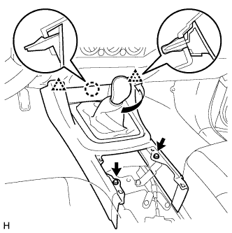 |
Remove the shift knob.
Remove the 2 screws <F>.
Disengage the 2 clips and claw, and remove the front console box.
| 19. REMOVE FRONT CONSOLE BOX (for Automatic Transmission on Bench Seat Type) |
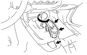 |
Remove the shift knob.
Remove the box bottom mat.
Remove the 2 instrument panel cup holders.
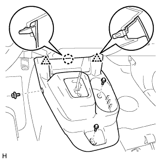 |
Remove the clip and 2 bolts <A>.
Disengage the 2 clips and claw, and remove the front console box.
| 20. REMOVE FRONT CONSOLE BOX (for Manual Transmission on Bench Seat Type) |
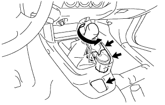 |
Remove the shift knob.
Remove the box bottom mat.
Remove the 2 instrument panel cup holders.
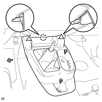 |
Remove the clip and 2 bolts <A>.
Disengage the 2 clips and claw, and remove the front console box.
| 21. REMOVE AIR CONDITIONER CONTROL ASSEMBLY |
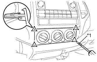 |
Using a screwdriver with its tip wrapped in protective tape, disengage the 4 clips and remove the air conditioner control assembly.
| *1 | Protective Tape |
Disconnect the 2 connectors.
| 22. REMOVE RADIO RECEIVER ASSEMBLY WITH BRACKET (w/o Navigation System) |
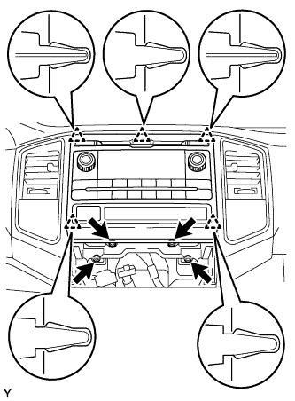 |
Remove the 4 bolts.
Disengage the 5 clips and remove the radio receiver assembly with bracket.
Disconnect the plug.
Disconnect all the connectors.
| 23. REMOVE RADIO AND DISPLAY RECEIVER ASSEMBLY WITH BRACKET (w/ Navigation System) |
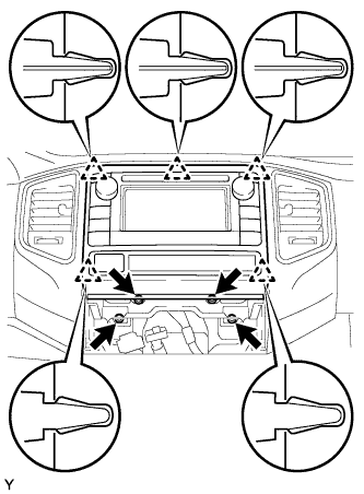 |
Remove the 4 bolts.
Disengage the 5 clips and remove the radio and display receiver assembly with bracket.
Disconnect all the connectors.
| 24. SEPARATE HOOD LOCK CONTROL LEVER SUB-ASSEMBLY |
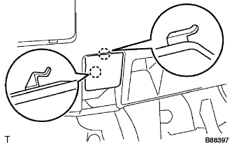 |
Disengage the 2 claws.
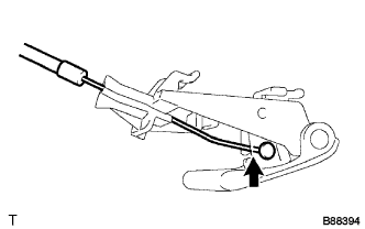 |
Disconnect the hood lock control cable assembly and remove the hood lock control lever sub-assembly.
| 25. REMOVE NO. 1 LOWER INSTRUMENT PANEL FINISH PANEL |
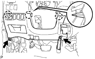 |
Remove the 2 bolts <B>.
Disengage the 3 clips and remove the lower No. 1 instrument panel finish panel.
Disconnect the connectors.
| 26. REMOVE INSTRUMENT CLUSTER FINISH PANEL SUB-ASSEMBLY |
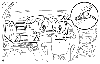 |
Remove the 2 clips.
Disengage the 6 clips and remove the instrument cluster finish panel sub-assembly.
Disconnect the connectors.
| 27. REMOVE COMBINATION METER ASSEMBLY |
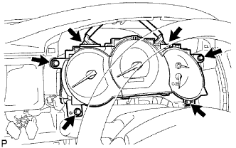 |
Remove the 4 screws and the combination meter assembly.
Disconnect the 2 connectors.
| 28. REMOVE INSTRUMENT CLUSTER CENTER FINISH PANEL SUB-ASSEMBLY |
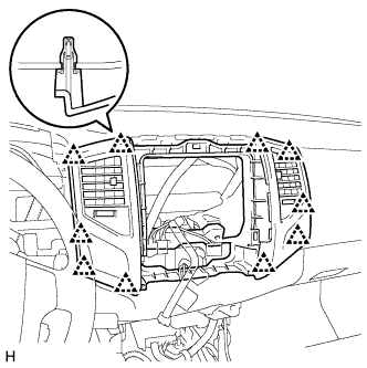 |
Disengage the 10 clips and remove the instrument cluster center finish panel sub-assembly.
| 29. REMOVE GLOVE COMPARTMENT DOOR ASSEMBLY |
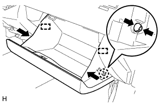 |
Disengage the claw and separate the glove compartment door stopper from the glove compartment door assembly.
Slightly deform the upper part of the glove compartment door assembly to release the 2 stoppers and open the glove compartment door assembly until it becomes horizontal.
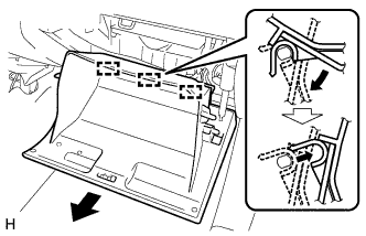 |
Pull the glove compartment door assembly toward the rear of the vehicle to release the 3 hinges and remove the glove compartment door assembly.
Remove the glove compartment door stopper.
| 30. REMOVE INSTRUMENT PANEL LOWER FINISH PANEL SUB-ASSEMBLY RH |
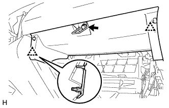 |
Remove the bolt <B>.
Disengage the 2 clips and remove the instrument panel lower finish panel sub-assembly RH.
| 31. REMOVE LOWER INSTRUMENT PANEL LH |
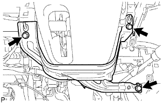 |
Remove the 3 bolts <B> and the lower instrument panel LH.
| 32. REMOVE INSTRUMENT LOWER COVER SUB-ASSEMBLY |
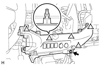 |
Remove the bolt <B>.
Disengage the 5 clips and remove the instrument lower cover sub-assembly.
Disconnect the connectors.
| 33. REMOVE INSTRUMENT SIDE PANEL RH |
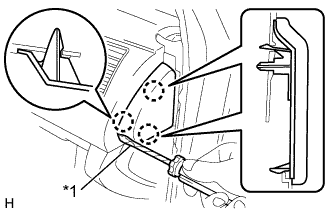 |
Using a screwdriver, disengage the 3 claws and remove the instrument side panel RH.
| *1 | Protective Tape |
| 34. DISCONNECT PASSENGER AIRBAG CONNECTOR |
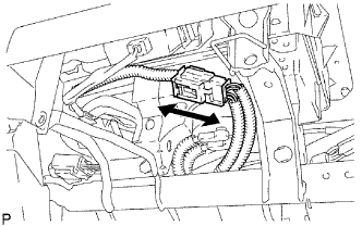 |
Disconnect the airbag connector.
| 35. REMOVE INSTRUMENT PANEL PASSENGER AIRBAG ASSEMBLY |
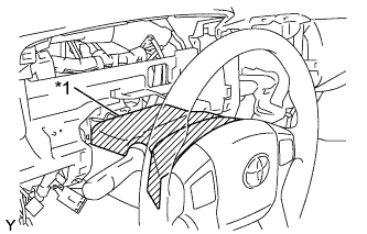 |
Tape the steering column cover upper and steering wheel sub-assembly with protective tape.
| *1 | Protective Tape |
Disengage the 4 clamps and disconnect the 4 connectors.
Remove the 8 bolts, nut and instrument panel sub-assembly with passenger airbag assembly.
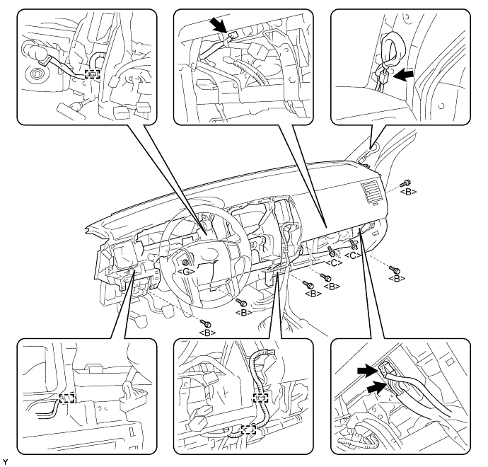
| 36. REMOVE INSTRUMENT PANEL SUB-ASSEMBLY |
| 37. REMOVE RADIO ANTENNA CORD SUB-ASSEMBLY |
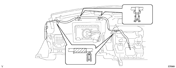
Disengage the 4 claws and remove the radio antenna cord sub-assembly.