FRONT DOOR (w/ Power Window) > REASSEMBLY |
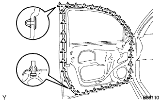
| 1. INSTALL FRONT DOOR WEATHERSTRIP LH (for Double Cab) |
|
Engage the 34 clips and install a new front door weatherstrip LH.
Remove the tab tape at both ends of 2-sided tape attached to the weather strip, and attach the weather strip to the door panel with the 2-sided tape.
| 2. INSTALL FRONT DOOR WEATHERSTRIP LH (for Access Cab) |
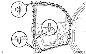 |
Engage the 36 clips and install a new front door weatherstrip LH.
Remove the tab tape at both ends of 2-sided tape attached to the weather strip, and attach the weather strip to the door panel with the 2-sided tape.
| 3. INSTALL FRONT DOOR CHECK ASSEMBLY LH |
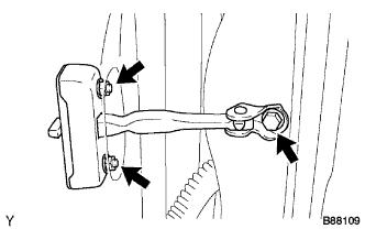 |
Apply MP grease to the sliding areas of the check.
Install the front door check assembly LH onto the door panel with the 2 nuts.
Apply adhesive to the threads of the bolt.
Install the front door check assembly LH onto the body panel with the bolt.
| 4. INSTALL FRONT DOOR OUTSIDE HANDLE FRAME SUB-ASSEMBLY LH |
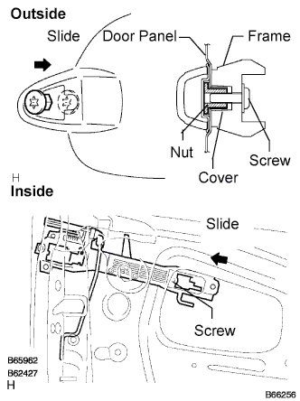 |
Using a torx socket wrench T30 , install the outside handle frame sub-assembly with the screw.
| 5. INSTALL FRONT DOOR OUTSIDE HANDLE ASSEMBLY LH |
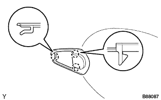 |
Engage the 3 claws and install the front door outside handle front pad.
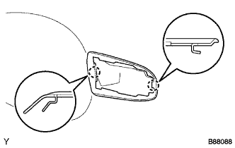 |
Engage the 2 claws and install the front door outside handle rear pad.
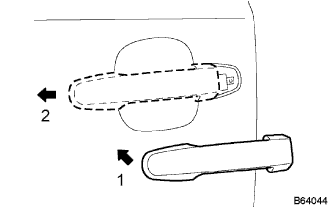 |
Pushing the front door handle assembly outside LH in the direction of the arrow marks shown in the illustration, install the front door outside handle assembly LH.
| 6. INSTALL FRONT DOOR LOCK ASSEMBLY LH |
Apply MP grease to the sliding and rotating areas of the front door lock assembly LH.
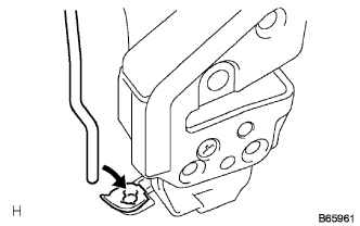 |
Insert the door lock open rod into the front door lock assembly, then set it to the door panel.
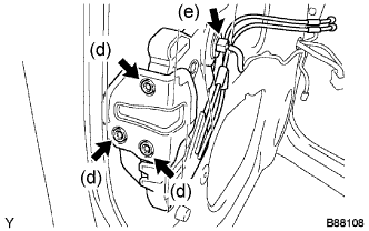 |
Apply adhesive to the threads of the 3 screws.
Using a torx socket wrench T30 , install the door lock assembly with the 3 screws.
Connect the front door lock connector.
| 7. INSTALL FRONT DOOR OUTSIDE HANDLE COVER LH |
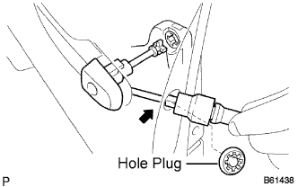 |
Using a torx socket wrench T30 , install the front door outside handle cover LH with the screw.
Install the hole plug.
| 8. INSTALL FRONT DOOR FRONT LOWER FRAME SUB-ASSEMBLY LH |
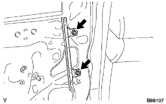 |
Install the front door front lower frame sub-assembly LH with the 2 nuts.
| 9. INSTALL FRONT DOOR REAR LOWER FRAME SUB-ASSEMBLY LH |
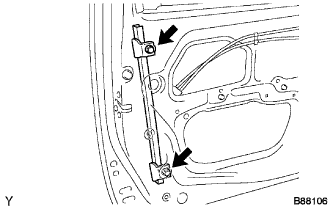 |
Install the front door rear lower frame sub-assembly LH with the 2 bolts.
| 10. INSTALL POWER WINDOW REGULATOR MOTOR ASSEMBLY LH |
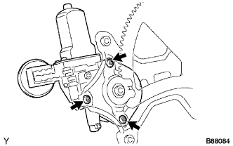 |
Align the matchmarks on the power window regulator motor gear and regulator gear.
Using a torx driver T25 , install the power window regulator motor assembly LH with the 3 screws.
| 11. INSTALL FRONT DOOR WINDOW REGULATOR SUB-ASSEMBLY LH |
Apply MP grease to the sliding and rotating parts of the front door window regulator assembly LH.
Loosely screw bolt A onto the front door window regulator sub-assembly LH.
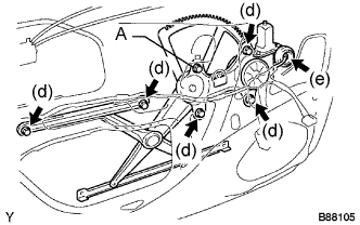 |
Insert the front door window regulator into the door panel. Use bolt A to hang the front door window regulator on the door panel.
Install the front door window regulator with the 5 bolts, and then tighten bolt A.
Connect the front door power window regulator connector.
| 12. INSTALL FRONT DOOR GLASS RUN LH |
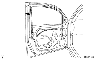 |
Install the front door glass run LH.
| 13. INSTALL FRONT DOOR GLASS SUB-ASSEMBLY LH |
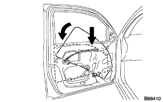 |
Insert the front door glass sub-assembly LH into the door panel along the glass run as indicated by the arrow marks in the illustration.
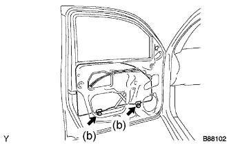 |
Install the front door glass sub-assembly LH into the front door window regulator sub-assembly LH with the 2 bolts.
Check the operation of the power window.
Connect the power window switch to the wire harness and turn the ignition switch to ON.
Repeat UP and DOWN operations several times manually.
| 14. INSTALL FRONT DOOR INSIDE PANEL PLATE LH |
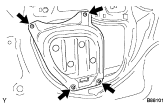 |
Install the front door inside panel plate LH with the 4 screws.
| 15. INSTALL FRONT DOOR BELT MOULDING LH |
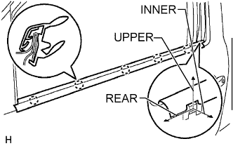 |
Engage the 5 claws and install a new front door belt moulding.
| 16. INSTALL OUTER REAR VIEW MIRROR ASSEMBLY LH |
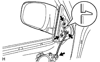 |
Engage the claw and install the outer rear view mirror.
Tighten the 3 nuts.
Connect the outer rear view mirror connector (w/ Power Mirror).
| 17. INSTALL FRONT DOOR SERVICE HOLE COVER LH |
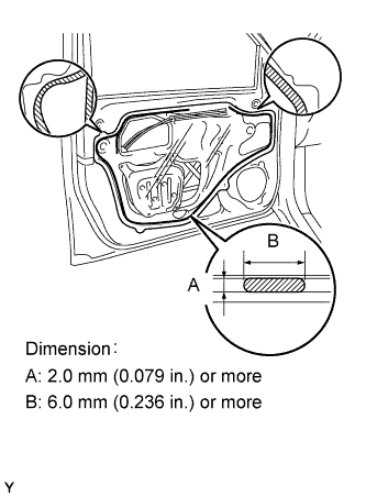 |
Apply butyl tape to the door panel, then install the front door service hole cover LH as shown in the illustration.
| 18. INSTALL FRONT DOOR INSIDE HANDLE SUB-ASSEMBLY LH |
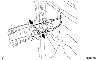 |
Connect the 2 cables to the front door inside handle sub-assembly LH.
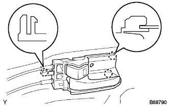 |
Engage the 3 claws and install the front door inside handle sub-assembly LH onto the door panel.
| 19. INSTALL NO. 1 DOOR TRIM BRACKET RH |
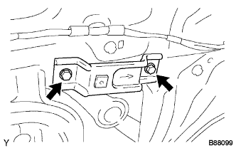 |
Install the No. 1 door trim bracket with the 2 screws.
| 20. INSTALL FRONT NO. 1 SPEAKER BRACKET |
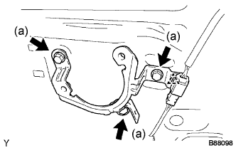 |
Install the front No. 1 speaker bracket with the 3 screws.
Connect the wire harness clamp and connector.
| 21. INSTALL FRONT NO. 2 SPEAKER ASSEMBLY |
| 22. INSTALL FRONT NO. 1 SPEAKER ASSEMBLY |
| 23. INSTALL FRONT DOOR TRIM PANEL ASSEMBLY LH |
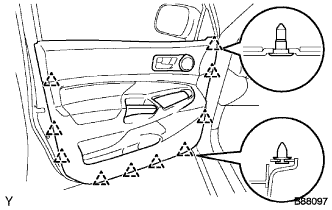 |
Engage the 10 clips and install the front door trim panel assembly LH.
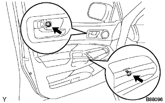 |
Install the 2 screws.
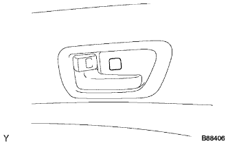 |
Close the cover.
| 24. INSTALL FRONT DOOR LOWER FRAME BRACKET GARNISH LH |
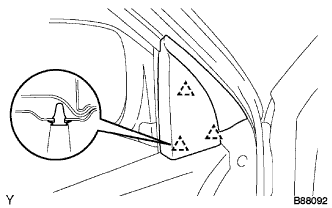 |
Engage the 3 clips and install the front lower frame bracket garnish LH.
| 25. INSTALL POWER WINDOW REGULATOR MASTER SWITCH ASSEMBLY (for Double Cab) |
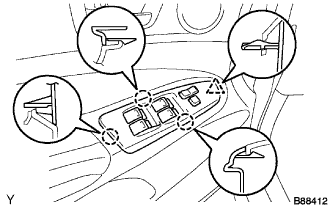 |
Connect the connector.
Engage the 3 claws and clip, and install the power window regulator master switch assembly.
| 26. INSTALL POWER WINDOW REGULATOR MASTER SWITCH ASSEMBLY (for Access Cab) |
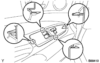 |
Connect the connector.
Engage the 3 claws and clip, and install the power window regulator master switch assembly.
| 27. INSTALL POWER WINDOW REGULATOR SWITCH ASSEMBLY |
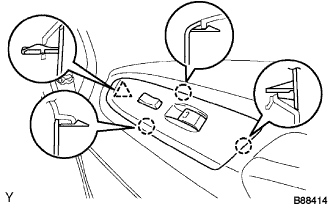 |
Connect the connector.
Engage the 3 claws and clip, and install the power window regulator switch assembly.
| 28. CONNECT CABLE TO NEGATIVE BATTERY TERMINAL |