Home › BODY ELECTRICAL › LIGHTING › TURN SIGNAL FLASHER ASSEMBLY

TURN SIGNAL FLASHER ASSEMBLY > ON-VEHICLE INSPECTION

for Preparation Click here


1. INSPECT TURN SIGNAL FLASHER ASSEMBLY


  1. w/o Daytime Running Light System and Towing Hitch:


    1. Check the power source circuit and ground circuit.
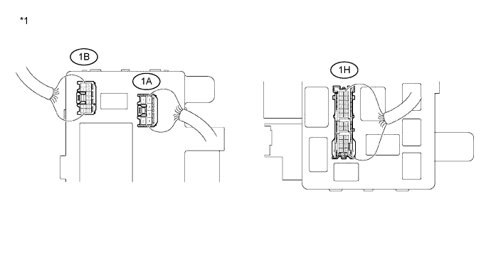

      E232390E01


      Text in Illustration 
      *1
      Instrument Panel Junction Block
      -
      -
      1. Measure the voltage according to the value(s) in the table below.
        Standard Voltage:

        Tester Connection
        Switch Condition
        Specified Condition
        1A-4 - Body ground
        Ignition switch ON
        11 to 14 V
        1A-4 - Body ground
        Ignition switch OFF
        0 V
        1B-4 - Body ground
        Always
        11 to 14 V

      2. Measure the resistance according to the value(s) in the table below.

        Standard Resistance:

        Tester Connection
        Condition
        Specified Condition
        1H-18 - Body ground
        Always
        Below 1 Ω


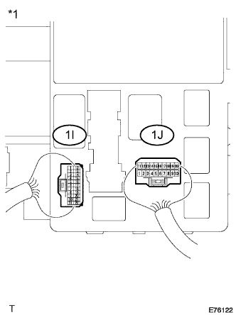
    2. E076122E02
    3. Check the output operation signal.
      Text in Illustration 
      *1
      Instrument Panel Junction Block

      1. Measure the voltage according to the value(s) in the table below.

        Standard Voltage:

        Tester Connection
        Switch Condition
        Specified Condition
        1I-11 - Body ground
        Hazard switch OFF → ON
        0 V → 11 to 14 V (60 to 120 times per minute)
        1I-11 - Body ground
        Turn signal switch (right turn) OFF → ON
        0 V → 11 to 14 V (60 to 120 times per minute)
        1I-11 - Body ground
        Turn signal switch (right turn) ON → OFF
        11 to 14 V (60 to 120 times per minute) → 11 to 14 V
        1I-12 - Body ground
        Hazard switch OFF → ON
        0 V → 11 to 14 V (60 to 120 times per minute)
        1I-12 - Body ground
        Turn signal switch (left turn) OFF → ON
        0 V → 11 to 14 V (60 to 120 times per minute)
        1I-12 - Body ground
        Turn signal switch (left turn) ON → OFF
        11 to 14 V (60 to 120 times per minute) → 11 to 14 V
        1J-8 - Body ground
        Turn signal switch (left turn) OFF → ON
        11 to 14 V → 0 V
        1J-18 - Body ground
        Turn signal switch (right turn) OFF → ON
        11 to 14 V → 0 V
        1J-11 - Body ground
        Hazard switch OFF → ON
        11 to 14 V → 0 V


  1. w/ Daytime Running Light System or Towing Hitch:


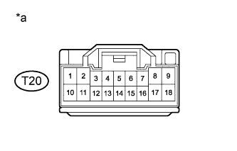
      E232385E01
    1. Check the power source circuit and ground circuit.
      Text in Illustration 
      *a
      Front view of wire harness connector
      (to Turn Signal Flasher Assembly)

      1. Disconnect the connector from the turn signal flasher assembly.
      2. Measure the voltage according to the value(s) in the table below.

        Standard Voltage:

        Tester Connection
        Switch Condition
        Specified Condition
        T20-3 - Body ground
        Ignition switch ON
        11 to 14 V
        T20-3 - Body ground
        Ignition switch OFF
        0 V
        T20-1 - Body ground
        Always
        11 to 14 V
        T20-11 - Body ground (*1)
        Always
        11 to 14 V

        *1: w/ Towing Hitch
      3. Measure the resistance according to the value(s) in the table below.

        Standard Resistance:

        Tester Connection
        Condition
        Specified Condition
        T20-4 - Body ground
        Always
        Below 1 Ω

    2. Check the output operation signal.


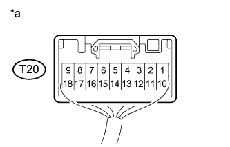
      1. E232391E01
        Connect the connector to the turn signal flasher assembly.
        Text in Illustration 
        *a
        Component with harness connected
        (Turn Signal Flasher Assembly)
      2. Measure the voltage according to the value(s) in the table below.

        Standard Voltage:

        Tester Connection
        Switch Condition
        Specified Condition
        T20-8 - Body ground
        Hazard switch OFF → ON
        0 V → 11 to 14 V (60 to 120 times per minute)
        T20-17 - Body ground
        T20-18 - Body ground (*1)
        T20-8 - Body ground
        Turn signal switch (right turn) OFF → ON
        0 V → 11 to 14 V (60 to 120 times per minute)
        T20-17 - Body ground
        T20-18 - Body ground (*1)
        T20-8 - Body ground
        Turn signal switch (right turn) ON → OFF
        11 to 14 V (60 to 120 times per minute) → 11 to 14 V
        T20-17 - Body ground
        T20-18 - Body ground (*1)
        T20-2 - Body ground
        Hazard switch OFF → ON
        0 V → 11 to 14 V (60 to 120 times per minute)
        T20-9 - Body ground (*1)
        T20-10 - Body ground
        T20-2 - Body ground
        Turn signal switch (left turn) OFF → ON
        0 V → 11 to 14 V (60 to 120 times per minute)
        T20-9 - Body ground (*1)
        T20-10 - Body ground
        T20-2 - Body ground
        Turn signal switch (left turn) ON → OFF
        11 to 14 V (60 to 120 times per minute) → 11 to 14 V
        T20-9 - Body ground (*1)
        T20-10 - Body ground
        T20-6 - Body ground
        Turn signal switch (left turn) OFF → ON
        11 to 14 V → 0 V
        T20-7 - Body ground
        Turn signal switch (right turn) OFF → ON
        11 to 14 V → 0 V
        T20-12 - Body ground
        Hazard switch OFF → ON
        11 to 14 V → 0 V
        T20-16 - Body ground (*1)
        Depress brake pedal
        11 to 14 V

        *1: w/ Towing Hitch