MANUAL TRANSMISSION ASSEMBLY > INSTALLATION |
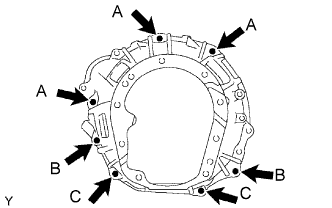
| 1. INSTALL MANUAL TRANSMISSION UNIT ASSEMBLY |
|
Align the input shaft with the clutch disc and install the transmission unit assembly onto the engine.
Install the 7 bolts.
| 2. CONNECT WIRE HARNESS |
Connect the wire harness clamp to the transmission assembly.
Connect the back-up lamp switch connector.
Connect the speed sensor connector.
| 3. INSTALL NO. 1 ENGINE MOUNTING INSULATOR REAR |
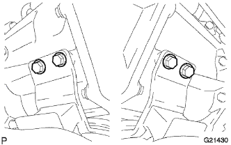 |
Install the engine mount insulator rear No. 1 onto the transmission assembly with 4 bolts.
| 4. INSTALL NO. 3 FRAME CROSSMEMBER SUB-ASSEMBLY |
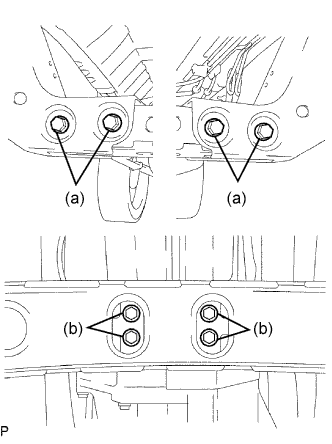 |
Install the frame crossmember sub-assembly No. 3 with the 8 bolts and nuts.
Install the 4 bolts onto the engine mounting insulator rear No. 1.
| 5. INSTALL CLUTCH RELEASE CYLINDER ASSEMBLY |
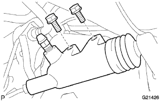 |
Install the clutch release cylinder assembly with the 2 bolts.
| 6. INSTALL STARTER ASSEMBLY |
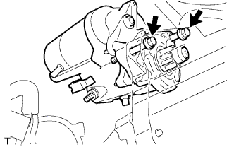 |
Install the starter with the 2 bolts.
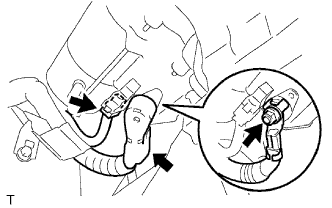 |
Connect the starter connector.
Install the starter wire harness with the nut.
Install the terminal cap.
| 7. INSTALL MANIFOLD STAY |
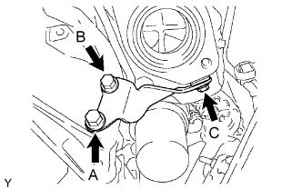 |
Install the manifold stay with the 3 bolts.
| 8. INSTALL PROPELLER WITH CENTER BEARING SHAFT ASSEMBLY (for Access Cab) |
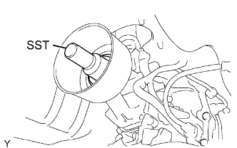 |
Remove SST from the extension housing.
Install the propeller shaft into the extension housing.
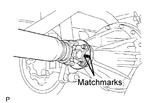 |
Align the matchmarks on the propeller shaft flange and differential flange.
Install the propeller shaft with the 4 bolts, 4 nuts and 4 washers.
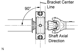 |
Provisionally install the center support bearing with the 2 mounting bolts.
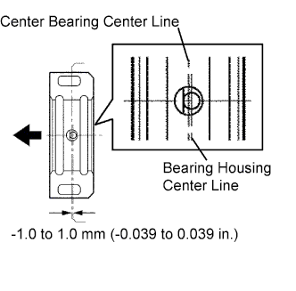 |
Adjust the center support bearing.
Torque the 2 bolts.
| 9. INSTALL PROPELLER SHAFT ASSEMBLY (for Regular Cab) |
|
Remove SST from the extension housing.
Install the propeller shaft assembly into the extension housing.
|
Align the matchmarks on the propeller shaft flange and differential flange.
Install the propeller shaft assembly with the 4 bolts, 4 nuts and 4 washers.
| 10. INSTALL FRONT EXHAUST PIPE ASSEMBLY |
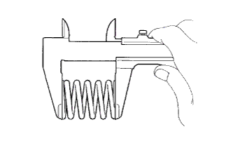 |
Check the free length.
Using vernier calipers, measure the free length of the compression spring.
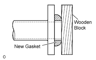 |
Using a wooden block and plastic-faced hammer, tap in a new gasket until it is flush with the exhaust manifold.
Install the exhaust pipe front into the exhaust pipe support.
Tighten the 2 bolts and 2 compression springs.
| 11. ADD MANUAL TRANSMISSION OIL |
| 12. ADJUST MANUAL TRANSMISSION OIL |
 |
Park the vehicle in a level place.
Remove the transmission filler plug and gasket.
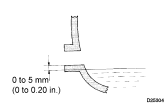
Check that the oil surface is within 5 mm (0.20 in.) of the lowest point of the transmission filler plug opening.
Check for oil leakage when the oil level is low.
Install the transmission filler plug and a new gasket.
| 13. INSTALL NO. 2 ENGINE UNDER COVER SUB-ASSEMBLY |
Install the engine under cover No. 2 with the 4 bolts.
| 14. INSTALL FLOOR SHIFT SHIFT LEVER ASSEMBLY |
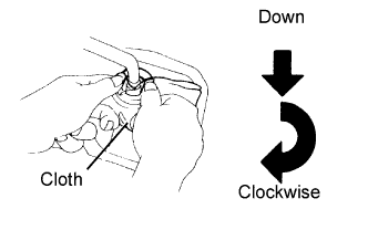 |
Cover the shift lever cap with a cloth.
While pressing down on the shift lever cap, turn it clockwise to install.
| 15. INSTALL SHIFT LEVER BOOT ASSEMBLY |
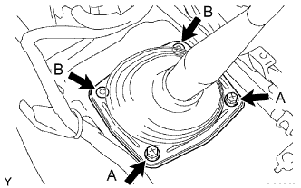 |
Install the shift lever boot assembly with the 2 screws A and 2 clips B.
| 16. INSTALL FRONT CONSOLE BOX (for Bench Seat Type) |
Engage the 2 clips and claw, and install the front console box.
Install the clip and 2 bolts <A>.
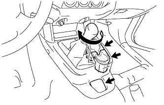 |
Install the 2 instrument panel cup holders.
Install the box bottom mat.
Install the shift knob.
| 17. INSTALL FRONT CONSOLE BOX (for Separate Seat Type) |
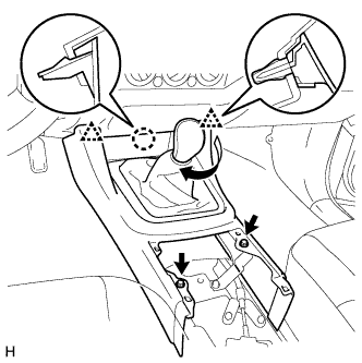 |
Engage the 2 clips and claw, and install the front console box.
Install the 2 screws <F>.
Install the shift knob.
| 18. INSTALL REAR CONSOLE BOX ASSEMBLY (for Separate Seat Type) |
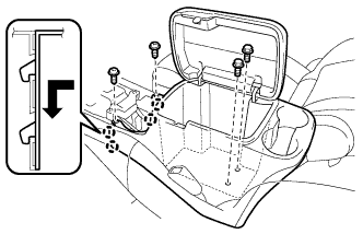 |
Engage the 4 claws and install the console box rear.
Install the 2 screws <F> and 2 bolts <B>.
Install the console box carpet.
| 19. INSTALL CONSOLE UPPER REAR PANEL SUB-ASSEMBLY (for Separate Seat Type) |
Engage the 4 clips and claw, and install the console upper panel sub-assembly.
| 20. CONNECT CABLE TO NEGATIVE BATTERY TERMINAL |
| 21. CHECK FOR MANUAL TRANSMISSION OIL LEAKAGE |