Home › ENGINE · 2TR-FE › STARTING › STARTER

STARTER > INSPECTION

for Preparation Click here


1. INSPECT STARTER ARMATURE ASSEMBLY


G036820E02
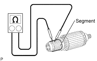
  1. Check the resistance.

    1. Using an ohmmeter, check the resistance between the segments of the commutator.
      Standard:
      1Ωor lower

      If the result is not as specified, replace the starter armature.


    G036821E02
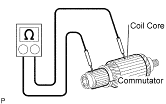
  1. Check the resistance.

    1. Using an ohmmeter, check the resistance between the commutator and armature coil core.

      Standard:
      10 kΩor higher

      If the result is not as specified, replace the starter armature.

  1. Check the commutator surface for dirt and burn.
    If the surface is dirty or burnt, smooth the surface with 400- grit sandpaper or a lathe.


    P010587E01
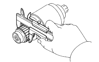
  1. Check the commutator diameter.

    1. Using vernier calipers, measure the commutator diameter.
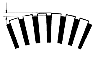
      Standard diameter:
      35.0 mm (1.378in.)

      Minimum diameter:
      34.0 mm (1.339in.)

      If the diameter is less than the minimum, replace the armature.


    ST00040E01
  1. Check the undercut depth.

    1. Check that the undercut portion between the segments is free of foreign objects and measure its depth.

      Standard undercut depth:
      0.7 mm (0.028in.)

      Minimum undercut depth:
      0.2 mm (0.008in.)

      If the undercut depth is less than the minimum, correct it with a hacksaw blade.


2. INSPECT STARTER YOKE ASSEMBLY


G036822E02
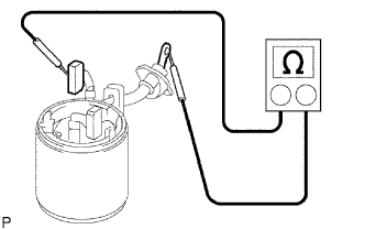
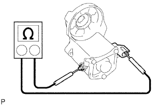
  1. Check the resistance.

    1. Using an ohmmeter, check the resistance between the lead wire and brushes.
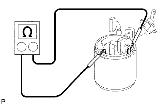
      Standard:
      1 Ωor lower

      If the result is not as specified, replace the starter yoke.


    G036823E01
  1. Check the resistance.

    1. Using an ohmmeter, check the resistance between shunt coil terminals (A) and (B).

      Standard:
      1.5 to 1.9 Ωat 20°C(68°F)

      If the result is not as specified, replace the starter yoke.


3. INSPECT BRUSH


A062430E03
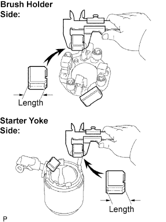
  1. Check the brush length.

    1. Using vernier calipers, measure the brush length

      Standard length:
      15.0 mm (0.591in.)

      Minimum length:
      9.0 mm (0.354in.)

      If the length is less than the minimum, replace the brush holder and starter yoke.


4. INSPECT STARTER BRUSH HOLDER ASSEMBLY


G036824E02
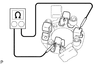
  1. Check the resistance.

    1. Using an ohmmeter, measure the resistance between the positive (+) and negative (-) brush holders.
      Standard:
      10 kΩ or higher

      If the result is not as specified, repair or replace the brush holder assembly.


    ST00019E03
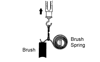
  1. Check the brush spring load.

    1. Check the pull scale reading as soon as the brush spring is separated from the brush.

      Standard spring load:
      21.5 to 27.5 N (2.2 to 2.8kgf,4.8 to 6.2lbf)

      Minimum spring load:
      12.7N(1.3kgf,2.9lbf)

      If the spring load is less than the minimum, replace the brush holder assembly.


5. INSPECT STARTER CLUTCH SUB-ASSEMBLY


P010821E04
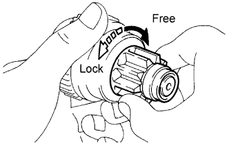
  1. Check the operation.

    1. Turn the clutch pinion gear clockwise and check that it turns freely. Try to rotate the clutch pinion gear counterclockwise and check that it locks.
      If necessary, replace the starter clutch.


6. INSPECT MAGNET STARTER SWITCH ASSEMBLY


G036853E01
  1. Check the resistance.

    1. Using an ohmmeter, measure the resistance between terminals 50 and C.
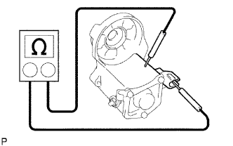
      Standard:
      1Ωor lower

      If the result is not as specified, replace the magnet switch


    G036854E01
  1. Check the resistance.

    1. Using an ohmmeter, measure the resistance between terminal 50 and the switch body.

      Standard:
      2.0Ωor lower

      If the result is not as specified, replace the magnet switch.