CRANKSHAFT POSITION SENSOR > REMOVAL |
| 1. DISCONNECT CABLE FROM NEGATIVE BATTERY TERMINAL |
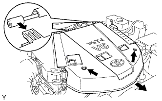
| 2. REMOVE V-BANK COVER |
|
Remove the 2 nuts, then remove the V-bank cover.
| 3. REMOVE FAN SHROUD |
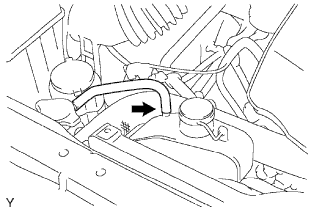 |
Disconnect the hose from the radiator reserve tank.
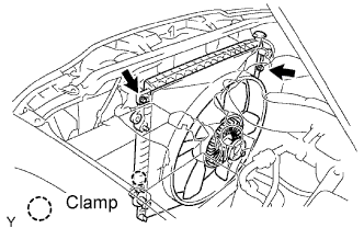 |
Remove the 2 cooler hoses from the clamp (with automatic transmission).
Remove the 4 nuts from the fan pulley.
Remove the fan and generator V belt .
Remove the 2 bolts from the fan shroud.
Remove the fan pulley and fan shroud.
| 4. REMOVE GENERATOR ASSEMBLY |
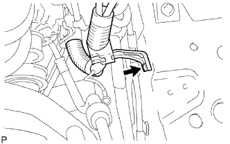 |
Disconnect the wire harness.
Remove the bolt and wire harness stay.
Disconnect the connector from the generator assembly.
Remove the terminal cap and nut.
Disconnect the wire harness from terminal B.
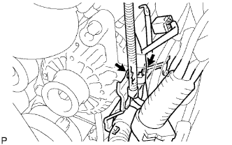 |
Remove the 2 bolts, then separate the wire harness clamp bracket from the generator assembly.
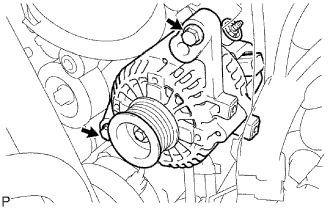 |
Remove the 2 bolts, then remove the generator assembly.
| 5. SEPARATE COOLER COMPRESSOR ASSEMBLY |
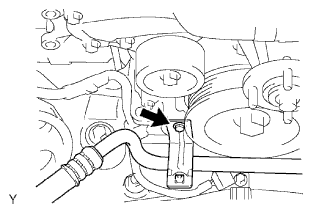 |
Remove the bolt, then separate the suction hose sub-assembly.
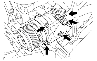 |
Disconnect the cooler compressor assembly connector.
Remove the 4 bolts, then separate the cooler compressor assembly from the V-ribbed belt tensioner assembly.
| 6. REMOVE CRANKSHAFT POSITION SENSOR |
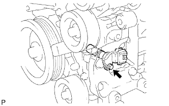 |
Disconnect the crankshaft position sensor connector.
Remove the bolt, then remove the crankshaft position sensor.