 |
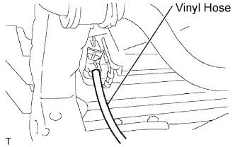
Install a vinyl hose onto the radiator side.
CAMSHAFT > REMOVAL |
| 1. DISCONNECT CABLE FROM NEGATIVE BATTERY TERMINAL |
| 2. REMOVE NO. 1 ENGINE UNDER COVER SUB-ASSEMBLY (for 4WD) |
Remove the 4 bolts, then remove the No. 1 engine under cover.
| 3. DRAIN ENGINE COOLANT |
Remove the 4 bolts, then remove the engine under cover No. 1. (PRE RUNNER AND 4WD TYPE)
|
Install a vinyl hose onto the radiator side.
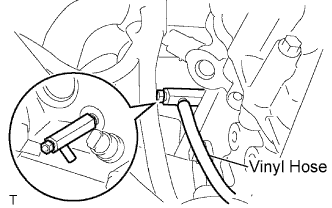 |
Install a vinyl hose onto the engine side.
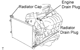 |
Loosen the engine drain plug.
Loosen the radiator drain plug.
Remove the radiator cap and drain coolant.
Drain the coolant from the reservoir tank.
| 4. REMOVE RADIATOR SUPPORT TO FRAME SEAL LH |
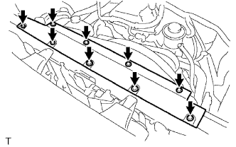 |
Disengage the 9 clips, then remove the radiator support to frame seal LH.
| 5. REMOVE FAN SHROUD |
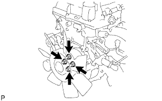 |
Loosen the 4 nuts shown in the illustration.
Remove the fan and generator V belt.
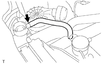 |
Disconnect the radiator reserve tank hose from the radiator.
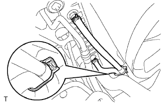 |
Disconnect the oil cooler inlet and outlet hoses from the fan shroud. (for Automatic Transmission)
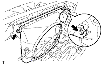 |
Remove the 2 bolts shown in the illustration.
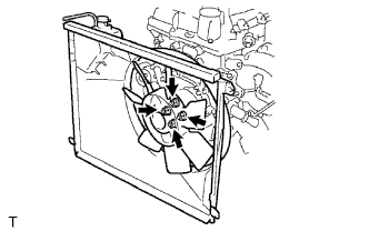 |
Remove the 4 nuts, then remove the fan shroud and fan with fluid coupling together.
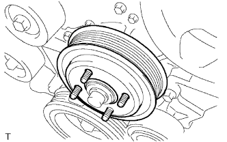 |
Remove the fan pulley.
| 6. REMOVE AIR CLEANER CAP SUB-ASSEMBLY |
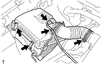 |
Disconnect the mass air flow meter connector.
Disconnect the wire harness clamp.
Loosen the hose clamp bolt, then disconnect the air cleaner hose No. 1.
Disconnect the 2 air cleaner clamps.
Remove the air cleaner cap together with the air cleaner hose No. 1.
| 7. REMOVE INTAKE AIR CONNECTOR |
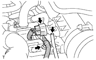 |
Disconnect the pressure sensor connector.
Disengage the wire harness clamp.
Disconnect the vacuum hose.
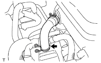 |
Disconnect the No. 2 ventilation hose.
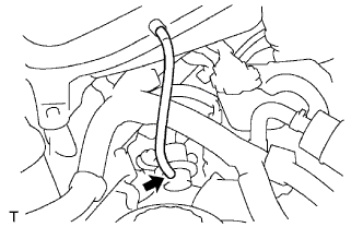 |
Disconnect the vacuum hose.
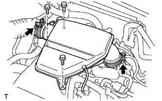 |
Loosen the 2 hose clamp bolts.
Remove the 3 bolts, then remove the intake air connector.
| 8. REMOVE CYLINDER HEAD COVER SUB-ASSEMBLY |
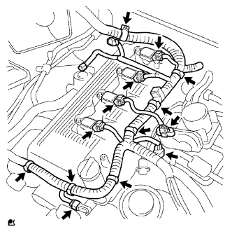 |
Disconnect the ignition coil connectors.
Disconnect the throttle with motor body connector.
Disconnect the VSV connector.
Disconnect the camshaft position sensor connector.
Disconnect the engine wire harness clamps.
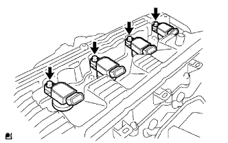 |
Remove the bolts, then remove the ignition coils.
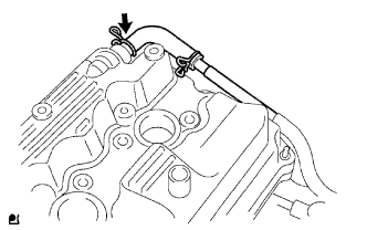 |
Disconnect the ventilation hose.
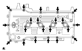 |
Remove the 19 bolts and 2 nuts, then remove the cylinder head cover.
| 9. REMOVE TIMING CHAIN GUIDE |
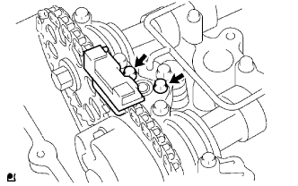 |
Remove the 2 bolts, then remove the timing chain guide.
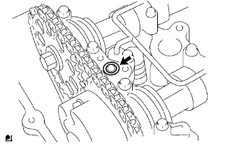 |
Remove the O-ring.
| 10. REMOVE CAMSHAFT |
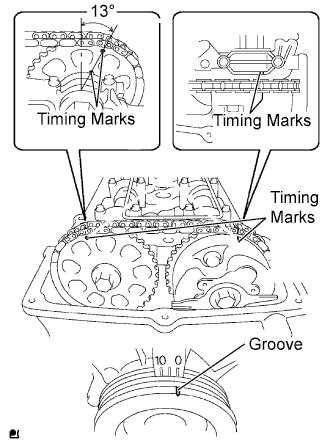 |
Set the No. 1 cylinder to the TDC/compression.
Turn the crankshaft pulley clockwise and align its timing mark notch with the timing mark "0".
Check that the timing marks of the camshaft timing gear are located as illustrated.
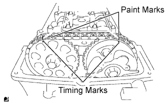 |
Place paint marks on the timing chain plates that align with timing marks of the camshaft timing gear.
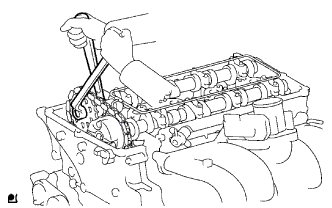 |
Hold the hexagonal lobe of the No. 2 camshaft with an adjustable wrench.
Loosen the bolt.
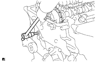 |
Using 10 mm socket hexagon wrench, remove the head straight screw plug.
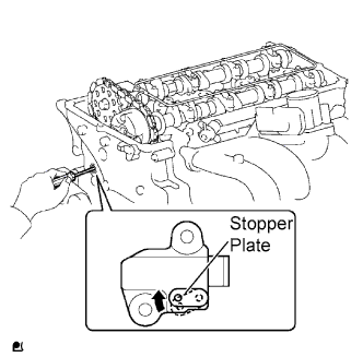 |
Insert a screwdriver into the service hole of the chain tensioner to hold the stopper plate of the chain tensioner lifted up.
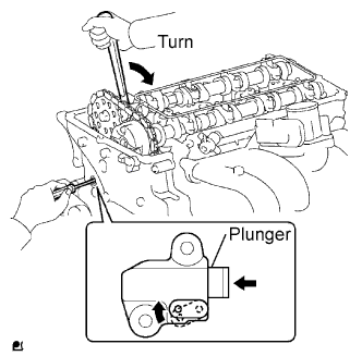 |
While keeping the stopper plate of the chain tensioner lifted up, slightly rotate the hexagonal lobe of the No. 2 camshaft clockwise with an adjustable wrench so the plunger of the chain tensioner is pushed.
Keeping the adjustable wrench installed, remove the screwdriver with the plunger pushed in.
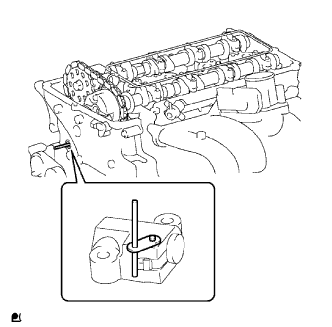 |
Insert a 3.0 mm (0.118 in.) diameter bar into the hole of the stopper plate with the stopper plate of the chain tensioner lifted down and locked.
Secure the 3.0 mm (0.118 in.) diameter bar with tape.
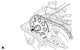 |
Remove the bolt, then remove the camshaft timing gear.
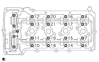 |
Using several steps, uniformly loosen and remove the 21 bearing cap bolts in the sequence shown in the illustration.
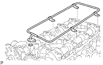 |
Remove the camshaft oil delivery pipe and O-ring.
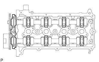 |
Remove the camshaft bearing cap No. 1 and 8 camshaft bearing caps No. 2.
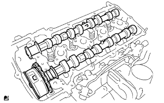 |
Remove the camshaft and No. 2 camshaft.
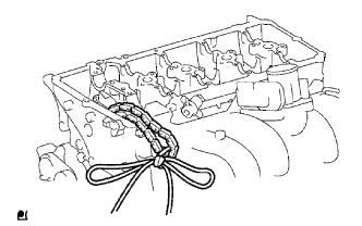 |
Tie the chain with a piece of string or wire.
| 11. REMOVE CAMSHAFT TIMING GEAR ASSEMBLY |
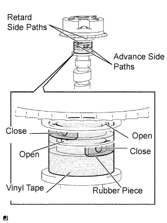 |
Clamp the camshaft in a vise, then check that the camshaft timing gear does not rotate.
Cover the 4 oil paths of the cam journal with vinyl tape as shown in the illustration.
Puncture the tape covering the advance side path and retard side path on the opposite side.
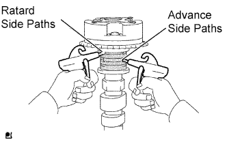 |
Apply air pressure at approximately 200 kPa (2.0 kgf/cm2, 29 psi) into the 2 paths (the advance side path and retard side path) from the 2 punctures.
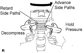 |
Confirm that the camshaft timing gear revolves in the advance direction when reducing the air pressure on the retard side path.
When the camshaft timing gear reaches the most advanced position, release the air pressure on the retard side path, then release the air pressure on the advance side path.
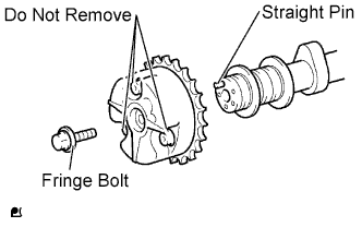 |
Remove the fringe bolt of the camshaft timing gear.