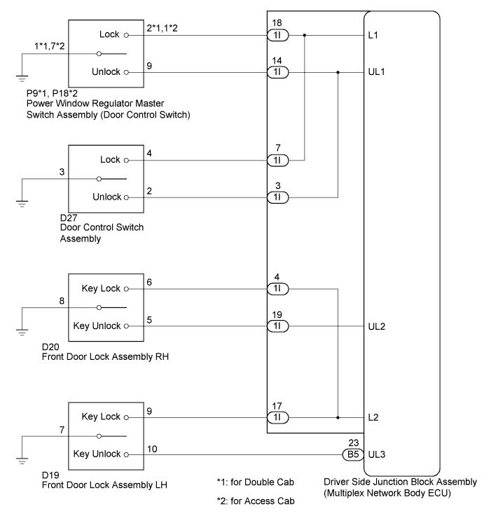
POWER DOOR LOCK CONTROL SYSTEM > All Doors cannot be Locked / Unlocked Simultaneously |
| 1.CHECK OPERATION (ALL DOORS LOCK/ UNLOCK) |
All doors can be locked/unlocked at once using the following:
Proceed to the next step according to the symptom if all the doors cannot be locked / unlocked at once.
| Result | Proceed to |
| All doors cannot be locked/unlocked at once using door control switch on power window regulator master switch assembly | A |
| All doors cannot be locked/unlocked at once using door control switch assembly | B |
| All doors cannot be locked/unlocked at once using door key cylinder on front door LH | C |
| All doors cannot be locked/unlocked at once using door key cylinder on front door RH | D |
|
| ||||
|
| ||||
|
| ||||
| A | |
 |
| 2.INSPECT POWER WINDOW REGULATOR MASTER SWITCH ASSEMBLY (DOOR CONTROL SWITCH) |
for Double Cab
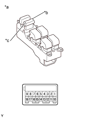 |
Remove the power window regulator master switch assembly.
Measure the resistance according to the value(s) in the table below.
| Tester Connection | Switch Condition | Specified Condition |
| 2 - 1 | LOCK | Below 1 Ω |
| OFF | 10 kΩ or higher | |
| 9 - 1 | UNLOCK | Below 1 Ω |
| OFF | 10 kΩ or higher |
| *a | Component without harness connected (Power Window Regulator Master Switch Assembly) |
| *b | LOCK |
| *c | UNLOCK |
Install the power window regulator master switch assembly.
for Access Cab
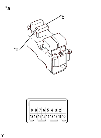 |
Remove the power window regulator master switch assembly.
Measure the resistance according to the value(s) in the table below.
| Tester Connection | Switch Condition | Specified Condition |
| 1 - 7 | LOCK | Below 1 Ω |
| OFF | 10 kΩ or higher | |
| 9 - 7 | UNLOCK | Below 1 Ω |
| OFF | 10 kΩ or higher |
| *a | Component without harness connected (Power Window Regulator Master Switch Assembly) |
| *b | LOCK |
| *c | UNLOCK |
Install the power window regulator master switch assembly.
|
| ||||
| OK | |
|
| 3.CHECK HARNESS AND CONNECTOR (DRIVER SIDE JUNCTION BLOCK ASSEMBLY - POWER WINDOW REGULATOR MASTER SWITCH ASSEMBLY) |
for Double Cab
Disconnect the 1I driver side junction block assembly (multiplex network body ECU) connector.
Disconnect the P9 power window regulator master switch assembly connector.
Measure the resistance according to the value(s) in the table below.
| Tester Connection | Condition | Specified Condition |
| 1I-18 (L1) - P9-2 | Always | Below 1 Ω |
| 1I-14 (UL1) - P9-9 | Always | Below 1 Ω |
| P9-1 - Body ground | Always | Below 1 Ω |
| 1I-18 (L1) - Body ground | Always | 10 kΩ or higher |
| 1I-14 (UL1) - Body ground | Always | 10 kΩ or higher |
Reconnect the driver side junction block assembly (multiplex network body ECU) connector.
Reconnect the power window regulator master switch assembly connector.
for Access Cab
Disconnect the 1I driver side junction block assembly (multiplex network body ECU) connector.
Disconnect the P18 power window regulator master switch assembly connector.
Measure the resistance according to the value(s) in the table below.
| Tester Connection | Condition | Specified Condition |
| 1I-18 (L1) - P18-1 | Always | Below 1 Ω |
| 1I-14 (UL1) - P18-9 | Always | Below 1 Ω |
| P18-7 - Body ground | Always | Below 1 Ω |
| 1I-18 (L1) - Body ground | Always | 10 kΩ or higher |
| 1I-14 (UL1) - Body ground | Always | 10 kΩ or higher |
Reconnect the driver side junction block assembly (multiplex network body ECU) connector.
Reconnect the power window regulator master switch assembly connector.
|
| ||||
| OK | ||
 | ||
| ||
| 4.INSPECT DOOR CONTROL SWITCH ASSEMBLY |
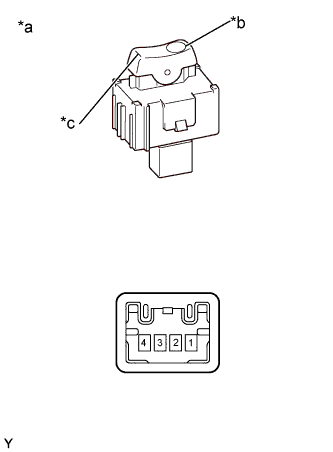 |
Remove the door control switch assembly.
Measure the resistance according to the value(s) in the table below.
| Tester Connection | Switch Condition | Specified Condition |
| 4 - 3 | LOCK | Below 1 Ω |
| OFF | 10 kΩ or higher | |
| 2 - 3 | UNLOCK | Below 1 Ω |
| OFF | 10 kΩ or higher |
| *a | Component without harness connected (Door Control Switch Assembly) |
| *b | LOCK |
| *c | UNLOCK |
Install the door control switch assembly.
|
| ||||
| OK | |
|
| 5.CHECK HARNESS AND CONNECTOR (DRIVER SIDE JUNCTION BLOCK ASSEMBLY (MULTIPLEX NETWORK BODY ECU) - DOOR CONTROL SWITCH ASSEMBLY) |
Disconnect the 1I driver side junction block assembly (multiplex network body ECU) connector.
Disconnect the D27 door control switch assembly connector.
Measure the resistance according to the value(s) in the table below.
| Tester Connection | Condition | Specified Condition |
| 1I-7 (L1) - D27-4 | Always | Below 1 Ω |
| 1I-3 (UL1) - D27-2 | Always | Below 1 Ω |
| D27-3 - Body ground | Always | Below 1 Ω |
| 1I-7 (L1) - Body ground | Always | 10 kΩ or higher |
| 1I-3 (UL1) - Body ground | Always | 10 kΩ or higher |
Reconnect the door control switch assembly connector.
Reconnect the driver side junction block assembly (multiplex network body ECU) connector.
|
| ||||
| OK | ||
| ||
| ||
| 6.INSPECT FRONT DOOR LOCK ASSEMBLY LH |
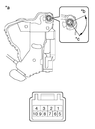 |
Remove the front door lock assembly LH.
Measure the resistance according to the value(s) in the table below.
| Tester Connection | Switch Condition | Specified Condition |
| 9 - 7 | LOCK | Below 1 Ω |
| OFF | 10 kΩ or higher | |
| 10 - 7 | UNLOCK | Below 1 Ω |
| OFF | 10 kΩ or higher |
| *a | Component without harness connected (Front Door Lock Assembly LH) |
| *b | LOCK |
| *c | UNLOCK |
Install the front door lock assembly LH.
|
| ||||
| OK | |
|
| 7.CHECK HARNESS AND CONNECTOR (DRIVER SIDE JUNCTION BLOCK ASSEMBLY (MULTIPLEX NETWORK BODY ECU) - FRONT DOOR LOCK ASSEMBLY LH) |
Disconnect the 1I and B5 driver side junction block assembly (multiplex network body ECU) connectors.
Disconnect the D19 front door lock assembly LH connector.
Measure the resistance according to the value(s) in the table below.
| Tester Connection | Condition | Specified Condition |
| 1I-17 (L2) - D19-9 | Always | Below 1 Ω |
| B5-23 (UL3) - D19-10 | Always | Below 1 Ω |
| D19-7 - Body ground | Always | Below 1 Ω |
| 1I-17 (L2) - Body ground | Always | 10 kΩ or higher |
| B5-23 (UL3) - Body ground | Always | 10 kΩ or higher |
Reconnect the front door lock assembly LH connector.
Reconnect the driver side junction block assembly (multiplex network body ECU) connectors.
|
| ||||
| OK | ||
| ||
| ||
| 8.INSPECT FRONT DOOR LOCK ASSEMBLY RH |
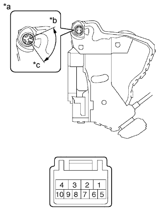 |
Remove the front door lock assembly RH.
Measure the resistance according to the value(s) in the table below.
| Tester Connection | Switch Condition | Specified Condition |
| 6 - 8 | LOCK | Below 1 Ω |
| OFF | 10 kΩ or higher | |
| 5 - 8 | UNLOCK | Below 1 Ω |
| OFF | 10 kΩ or higher |
| *a | Component without harness connected (Front Door Lock Assembly RH) |
| *b | LOCK |
| *c | UNLOCK |
Install the front door lock assembly RH.
|
| ||||
| OK | |
|
| 9.CHECK HARNESS AND CONNECTOR (DRIVER SIDE JUNCTION BLOCK ASSEMBLY (MULTIPLEX NETWORK BODY ECU) - FRONT DOOR LOCK ASSEMBLY RH) |
Disconnect the 1I driver side junction block assembly (multiplex network body ECU) connectors.
Disconnect the D20 front door lock assembly RH connector.
Measure the resistance according to the value(s) in the table below.
| Tester Connection | Condition | Specified Condition |
| 1I-4 (L2) - D20-6 | Always | Below 1 Ω |
| 1I-19 (UL2) - D20-5 | Always | Below 1 Ω |
| D20-8 - Body ground | Always | Below 1 Ω |
| 1I-4 (L2) - Body ground | Always | 10 kΩ or higher |
| 1I-19 (UL2) - Body ground | Always | 10 kΩ or higher |
Reconnect the front door lock assembly RH connector.
Reconnect the driver side junction block assembly (multiplex network body ECU) connectors.
|
| ||||
| OK | ||
| ||
| ||

