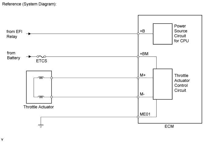
DTC P2118 Throttle Actuator Control Motor Current Range / Performance |
| DTC Code | DTC Detection Condition | Trouble Area |
| P2118 | Open in ETCS power source (+BM) circuit (1 trip detection logic) |
|
| Related DTCs | P2118: Throttle actuator power supply |
| Required Sensors/Components (Main) | Throttle actuator, throttle valve, ETCS fuse |
| Required Sensors/Components (Related) | None |
| Frequency of Operation | Continuous |
| Duration | 0.8 seconds |
| MIL Operation | Immediate |
| Sequence of Operation | None |
| Monitor runs whenever following DTCs not present | None |
| Battery voltage | 8 V or more |
| Electronic throttle actuator power | ON |
| Throttle actuator power supply voltage (+BM) | Less than 4 V |
| Throttle actuator power supply voltage (+BM) | 11 to 14 V |
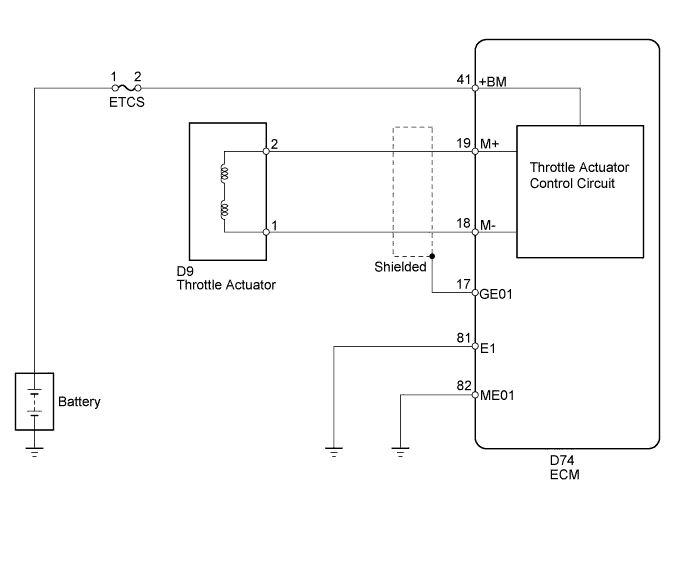
| 1.READ VALUE USING TECHSTREAM (+BM VOLTAGE) |
Connect the Techstream to the DLC3.
Turn the ignition switch to ON.
Turn the Techstream ON.
Enter the following menus: Powertrain / Engine and ECT / Data List / All Data / +BM Voltage.
Read the value displayed on the Techstream.
| Result | Proceed to |
| Less than 11 V or more than 14 V | A |
| 11 to 14 V | B |
|
| ||||
| A | |
 |
| 2.INSPECT FUSE (ETCS) |
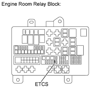 |
Remove the ETCS fuse from the engine room relay block.
Measure the resistance according to the value(s) in the table below.
| Tester Connection | Condition | Specified Condition |
| ETCS fuse | Always | Below 1 Ω |
|
| ||||
| OK | |
|
| 3.CHECK HARNESS AND CONNECTOR (ECM - ETCS FUSE, ETCS FUSE - BATTERY) |
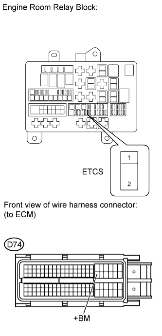 |
Check the harness and connector between the ETCS fuse and ECM.
Remove the ETCS fuse from the engine room relay block.
Disconnect the D74 ECM connector.
Measure the resistance according to the value(s) in the table below.
| Tester Connection | Condition | Specified Condition |
| ETCS fuse terminal 2 - D74-41 (+BM) | Always | Below 1 Ω |
| ETCS fuse terminal 2 or D74-41 (+BM) - Body ground | Always | 10 kΩ or higher |
Check the harness and connector between the ETCS fuse and positive battery cable.
Remove the ETCS fuse from the engine room relay block.
Disconnect the cable from the positive (+) battery terminal.
Measure the resistance according to the value(s) in the table below.
| Tester Connection | Condition | Specified Condition |
| Positive battery cable - ETCS fuse terminal 1 | Always | Below 1 Ω |
| Positive battery cable or ETCS fuse terminal 1 - Body ground | Always | 10 kΩ or higher |
|
| ||||
| OK | |
|
| 4.INSPECT ECM (+BM VOLTAGE) |
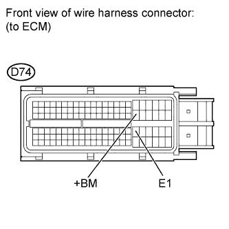 |
Disconnect the D74 ECM connector.
Measure the voltage according to the value(s) in the table below.
| Tester Connection | Condition | Specified Condition |
| D74-41 (+BM) - D74-81 (E1) | Always | 11 to 14 V |
|
| ||||
| OK | ||
 | ||
| ||
