CYLINDER BLOCK > INSPECTION |
| 1. INSPECT CYLINDER BLOCK SUB-ASSEMBLY |
![]() |
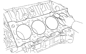
Clean the cylinder block.
Using a gasket scraper, remove all the gasket material from the top surface of the cylinder block.
Using a soft brush and solvent, thoroughly clean the cylinder block.
![]() |
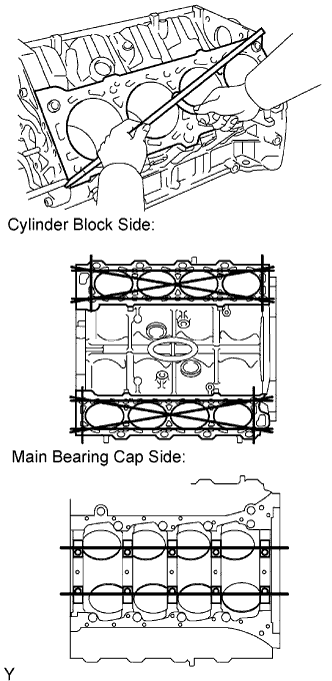
Using a precision straightedge and feeler gauge, measure the surfaces contacting the cylinder head and main bearing cap for warpage.
![]() |
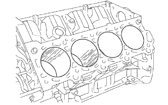
Visually check the cylinder for vertical scratches.
If deep scratches are present, rebore all 8 cylinders and replace all 8 pistons. If necessary, replace the cylinder block.
| 2. INSPECT CYLINDER BORE |
![]() |
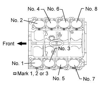
Inspect the cylinder bore diameter.
![]() |
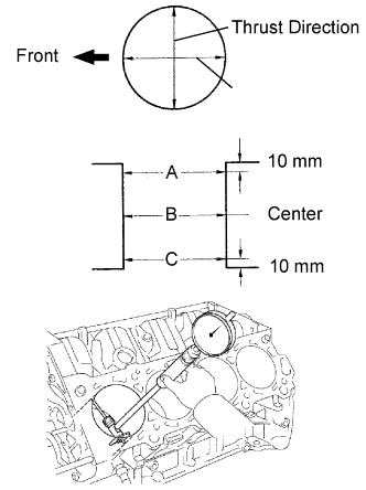
Using a cylinder gauge, measure the cylinder bore diameter at positions A, B and C in the thrust and axial directions.
| Measurement Position | Cylinder Bore Position |
| A | 10 mm (0.394 in.) from top edge |
| B | Center |
| C | 10 mm (0.394 in.) from bottom edge |
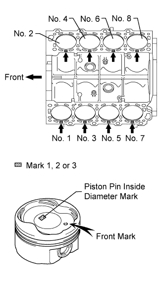
| Number Mark | Specified Condition |
| Mark 1 | 94.002 to 94.010 mm (3.7009 to 3.7011 in.) |
| Mark 2 | 94.010 to 94.023 mm (3.7011 to 3.7017 in.) |
| Mark 3 | 94.023 to 94.031 mm (3.7017 to 3.7020 in.) |
| 3. INSPECT PISTON SUB-ASSEMBLY WITH PIN |
Clean the piston.
![]() |
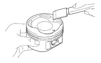
Using a gasket scraper, remove the carbon from the piston top.
![]() |
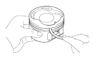
Using a groove cleaning tool or broken ring, clean the piston ring grooves.
![]() |
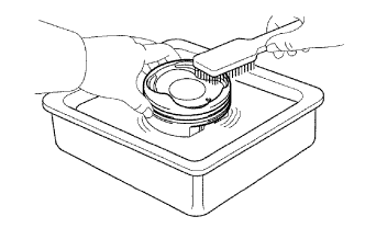
Using solvent and a brush, thoroughly clean the piston.
![]() |
Inspect the piston oil clearance.
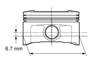
Using a micrometer, measure the piston diameter at a position that is 6.7 mm (0.264 in.) downward from the center of the piston pin hole (refer to the illustration).
| Number Mark | Specified Condition |
| Mark 1 | 93.942 to 93.952 mm (3.6985 to 3.6989 in.) |
| Mark 2 | 93.952 to 93.960 mm (3.6989 to 3.6992 in.) |
| Mark 3 | 93.960 to 93.970 mm (3.6992 to 3.6996 in.) |
Measure the cylinder bore diameter in the thrust directions.
![]() |
Subtract the piston diameter measurement from the cylinder bore diameter measurement.
Inspect the piston pin fit.
![]() |
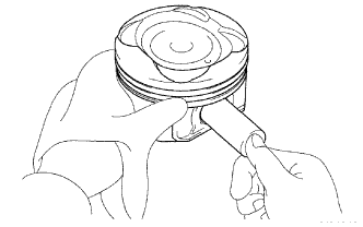
Heat the piston to approximately 60°C (140°F), and push the piston pin into the piston pin hole with your thumb.
| 4. INSPECT PISTON PIN OIL CLEARANCE |
Using a caliper gauge, measure the inside diameter of the piston pin hole.
| Mark | Specified Condition |
| A | 21.998 to 22.001 mm (0.86606 to 0.86618 in.) |
| B | 22.002 to 22.004 mm (0.86622 to 0.86629 in.) |
| C | 22.005 to 22.007 mm (0.86634 to 0.86642 in.) |
![]() |
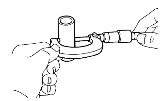
Using a micrometer, measure the piston pin diameter.
| Item | Specified Condition |
| A | 21.997 to 22.000 mm (0.86602 to 0.86614 in.) |
| B | 22.001 to 22.003 mm (0.86618 to 0.86626 in.) |
| C | 22.004 to 22.006 mm (0.86630 to 0.86638 in.) |
Subtract the piston pin diameter measurement from the piston pin hole diameter measurement.
![]() |
Inspect the piston pin oil clearance.
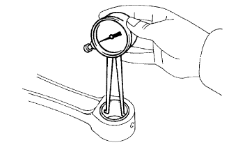
Using a caliper gauge, measure the inside diameter of the connecting rod bush.
Subtract the piston pin diameter measurement from the bush inside diameter measurement.
| 5. INSPECT PISTON RING SET |
![]() |
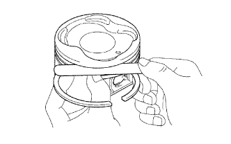
Inspect the piston ring groove clearance.
Using a feeler gauge, measure the clearance between a new piston ring and the wall of the ring groove.
| Piston Ring | Specified Condition |
| No. 1 | 0.030 to 0.080 mm (0.00181 to 0.00314 in.) |
| No. 2 | 0.020 to 0.060 mm (0.000787 to 0.00236 in.) |
![]() |
Inspect the piston ring end gap.
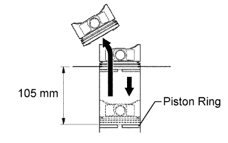
Insert the piston ring into the cylinder bore.
Using a piston, push the piston ring a little beyond the bottom of the ring travel, 105 mm (4.13 in.) from the top of the cylinder block.
![]() |
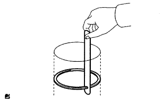
Using a feeler gauge, measure the end gap.
| End Gap | Specified Condition |
| No. 1 piston ring | 0.300 to 0.400 mm (0.0118 to 0.0157 in.) |
| No. 2 piston ring | 0.400 to 0.550 mm (0.0157 to 0.0217 in.) |
| Oil ring (Side rail) | 0.130 to 0.380 mm (0.00511 to 0.0150 in.) |
| End Gap | Specified Condition |
| No. 1 piston ring | 1.10 mm (0.0433 in.) |
| No. 2 piston ring | 1.30 mm (0.0512 in.) |
| Oil ring (Side rail) | 0.90 mm (0.0354 in.) |
| 6. INSPECT CONNECTING ROD SUB-ASSEMBLY |
![]() |
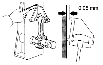
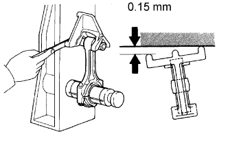
Using a rod aligner and feeler gauge, check the connecting rod alignment.
Check if the connecting rod is bent.
![]() |
Check if the connecting rod is twisted.
| 7. INSPECT CRANKSHAFT |
![]() |
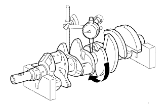
Inspect for circle runout.
Place the crankshaft on V-blocks.
Using a dial indicator, measure the circle runout at the center journal.
![]() |
Inspect the main journals and crank pins.
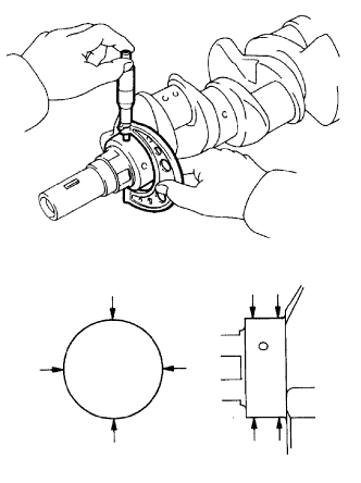
Using a micrometer, measure the diameter of each main journal and crank pin.
| Item | Specified Condition |
| Main journal | 66.988 to 67.000 mm (2.6373 to 2.6378 in.) |
| Crank pin | 51.982 to 52.000 mm (2.0465 to 2.0472 in.) |
Check each main journal and crank pin for taper and out of round as shown in the illustration.
| 8. INSPECT CONNECTING ROD BOLT |
![]() |
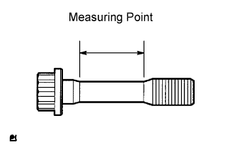
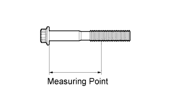
Using a vernier caliper, measure the tension portion of the connecting rod bolt.
| 9. INSPECT CRANKSHAFT BEARING CAP BOLT |
![]() |
Using a vernier caliper, measure the tension portion diameter of the main bearing cap bolt.
| 10. INSPECT NO. 1 OIL NOZZLE SUB-ASSEMBLY |
![]() |
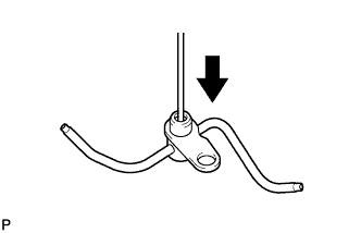
Push the check valve with a pin to check if it is stuck.
If stuck, replace the oil nozzle.
![]() |
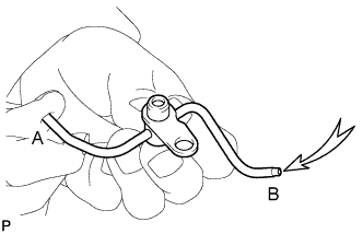
While covering A, apply air into B. Then check the oil nozzle for damage or clogging. Perform the check again while covering B and applying air into A.
If there is an air leak, repair or replace the oil nozzle.
If the oil nozzle is clogged, clean or replace it.
![]() |
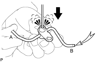
Push the check valve while covering A, and apply air into B. Check that air passes through the oil nozzle. Perform the check again while covering B, pushing the check valve and applying air into A.
If air cannot pass through, clean or replace the oil nozzle.