REPAIR INSTRUCTION > INITIALIZATION |
| PROCEDURES NECESSARY WHEN BATTERY TERMINAL IS DISCONNECTED / RECONNECTED |
| Necessary Procedures | Procedure Details | Effects / Inoperative Functions When Necessary Procedures are not Performed | Notes |
| Navigation system initialization | After turning the ignition switch on (IG), insert the map disc. | Navigation system | If the map disc is inside when disconnecting the cable from the battery terminal, this procedure is not necessary |
| PROCEDURES NECESSARY WHEN ECU OR OTHER PARTS ARE REPLACED |
| Replacement Part | Necessary Procedures | Effects / Inoperative Functions When Necessary Procedures are not Performed | Notes |
| ECM | Register VIN | DTC P0630 is output | - |
| Reset memory | Large shift shock | - |
| Tire pressure warning ECU |
|
| - |
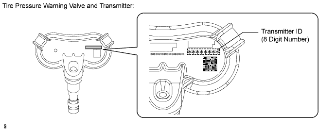
| Tire pressure warning valve and transmitter |
|
| Even if only one wheel is replaced, IDs for all 4 wheels must be registered. |
| Skid control ECU |
|
| - |
| Yaw rate sensor |
|
| - |
| Front Wheel Alignment Adjustment |
|
| Complete the adjustment of the steering wheel and wheel alignment, and then initialize the steering angle sensor. If the order is reversed, the steering wheel and wheel alignment will become misaligned. |
| Occupant classification ECU |
|
| - |
| Registration | Engine starting | - |
| Register recognition code | Wireless door lock operation | - |
| Inner rear view mirror |
|
| - |
| Initialize sliding roof system |
| - |
| DESCRIPTION |
Read VIN: Explains the VIN reading process in a flowchart. This process allows the VIN stored in the ECM to be read in order to confirm that the two VINs, provided with the vehicle and stored in the vehicle's ECM, are the same.
Write VIN: Explains the VIN writing process in a flowchart. This process allows the VIN to be input into the ECM. If the ECM is changed, or the ECM VIN and vehicle VIN do not match, the VIN can be registered, or overwritten in the ECM by following this procedure.
| READ VIN |
Confirm the vehicle VIN.
Connect Techstream to the DLC3.
Turn the ignition switch ON.
Turn the tester ON.
Enter the following menus: Powertrain / Engine and ECT / Utility / VIN / VIN Read.
| WRITE VIN |
Confirm the vehicle VIN.
Connect Techstream to the DLC3.
Turn the ignition switch ON.
Turn the tester ON.
Enter the following menus: Powertrain / Engine and ECT / Utility / VIN / VIN Write.
| RESET MEMORY |
Connect the Techstream to the DLC3.
Turn the ignition switch ON and push the tester switch ON.
Enter the following menus:
Select: Powertrain / Engine and ECT / Utility / Reset Memory.
| DESCRIPTION OF CODE REGISTRATION |
Before registration
In case of tire pressure warning ECU replacement:
In case of tire pressure warning valve and transmitter replacement:

| DESCRIPTION OF INITIALIZATION |
Perform initialization in the following cases:
Before initialization
Set the tire pressure of all tires to the specified value(s).
| INITIALIZATION PROCEDURE |
Turn the ignition switch to ON.
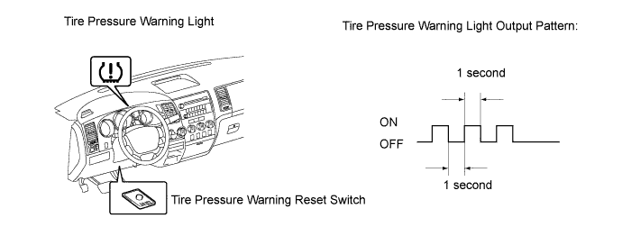
Press and hold the tire pressure warning reset switch for 3 seconds or more so that the tire pressure warning light blinks 3 times.

Turn the ignition switch off.
Connect the Techstream to the DLC3.
Turn the ignition switch to ON and the Techstream on.
Enter the following menus: Chassis / Tire Pressure Monitor / Data List.
![]() |
Confirm that the tire pressure data of all tires are displayed on the Techstream screen in order to check the completion.
| Tester Display | Measurement Item/Range | Normal Condition | Diagnostic Note |
| ID1 Tire Inflation Pressure | ID1 tire inflation pressure / min.: Absolute pressure / 100 kPa (1 kgf/cm2, 14 psi), Relative pressure / 0 kPa (0 kgf/cm2, 0 psi) max.: Absolute pressure / 449.35 kPa (4.5 kgf/cm2, 63 psi), Relative pressure / 349.35 kPa (3.6 kgf/cm2, 51 psi) | Actual tire inflation pressure | If 100 kPa (1 kgf/cm2, 14 psi) for the absolute pressure or 0 kPa (0 kgf/cm2, 0 psi) is displayed for the relative pressure, the data has not been received.* |
| ID2 Tire Inflation Pressure | ID2 tire inflation pressure / min.: Absolute pressure / 100 kPa (1 kgf/cm2, 14 psi), Relative pressure / 0 kPa (0 kgf/cm2, 0 psi) max.: Absolute pressure / 449.35 kPa (4.5 kgf/cm2, 63 psi), Relative pressure / 349.35 kPa (3.6 kgf/cm2, 51 psi) | Actual tire inflation pressure | If 100 kPa (1 kgf/cm2, 14 psi) for the absolute pressure or 0 kPa (0 kgf/cm2, 0 psi) is displayed for the relative pressure, the data has not been received.* |
| ID3 Tire Inflation Pressure | ID3 tire inflation pressure / min.: Absolute pressure / 100 kPa (1 kgf/cm2, 14 psi), Relative pressure / 0 kPa (0 kgf/cm2, 0 psi) max.: Absolute pressure / 449.35 kPa (4.5 kgf/cm2, 63 psi), Relative pressure / 349.35 kPa (3.6 kgf/cm2, 51 psi) | Actual tire inflation pressure | If 100 kPa (1 kgf/cm2, 14 psi) for the absolute pressure or 0 kPa (0 kgf/cm2, 0 psi) is displayed for the relative pressure, the data has not been received.* |
| ID4 Tire Inflation Pressure | ID4 tire inflation pressure / min.: Absolute pressure / 100 kPa (1 kgf/cm2, 14 psi), Relative pressure / 0 kPa (0 kgf/cm2, 0 psi) max.: Absolute pressure / 449.35 kPa (4.5 kgf/cm2, 63 psi), Relative pressure / 349.35 kPa (3.6 kgf/cm2, 51 psi) | Actual tire inflation pressure | If 100 kPa (1 kgf/cm2, 14 psi) for the absolute pressure or 0 kPa (0 kgf/cm2, 0 psi) is displayed for the relative pressure, the data has not been received.* |
| CLEAR ZERO POINT CALIBRATION DATA |
Connect the Techstream to the DLC3.
Turn the ignition switch ON.
Operate the Techstream to erase the codes (select "Reset Memory").
| PERFORM ZERO POINT CALIBRATION OF MASTER CYLINDER PRESSURE SENSOR AND DECELERATION SENSOR |
Enter Test Mode.
Turn the ignition switch OFF.
Check that the shift lever is in parking or neutral and apply the parking brake.
Connect the Techstream to the DLC3.
Turn the ignition switch ON.
Set the Techstream to test mode (select "Test Mode").
Obtain the zero points of the master cylinder pressure sensor and deceleration sensor.
Keep the vehicle stationary on a level surface for 1 second or more.
Check that the buzzer sounds for 3 seconds and DTC C1336 is erased.
Turn the ignition switch OFF.
| CLEAR ZERO POINT CALIBRATION DATA (WHEN USING SST CHECK WIRE) |
Turn the ignition switch ON.
![]() |
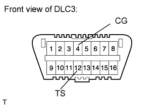
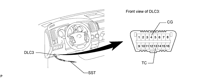
Using SST, connect and disconnect terminals 12 (TS) and 4 (CG) of the DLC3 4 times or more within 8 seconds.
Check that the VSC OFF indicator light comes on.
Using a check wire, perform the zero point calibration of the deceleration sensor.
| PERFORM ZERO POINT CALIBRATION OF MASTER CYLINDER PRESSURE SENSOR AND DECELERATION SENSOR (WHEN USING SST CHECK WIRE) |
Enter Test Mode.
Turn the ignition switch OFF.
Check that the shift lever is in parking or neutral and apply the parking brake.
![]() |
Using SST, connect terminals 12 (TS) and 4 (CG) of the DLC3.
Turn the ignition switch ON.
Obtain the zero points of the master cylinder pressure sensor and deceleration sensor.
Keep the vehicle stationary on a level surface for 1 second or more.
Check that the buzzer sounds for 3 seconds and DTC C1336 is erased.
Turn the ignition switch OFF.
| PERFORM INITIALIZATION OF STEERING ANGLE SENSOR |
Check that the steering wheel is in the centered position.
Disconnect the negative battery terminal for more than 2 seconds.
Reconnect the negative battery terminal.
| ZERO POINT CALIBRATION |
Zero point calibration procedures:
Check that all of the following conditions are met:
Adjust the seat position in accordance with the table below.
| Adjustment Item | Position |
| Slide Direction | Rearmost position |
| Reclining Angle | Upright position |
| Headrest Height | Lowest position |
| Lifter Height | Lowest position |
Connect the Techstream to the DLC3.
Turn the ignition switch ON.
Perform the zero point calibration by following the prompts on the tester screen.
| SENSITIVITY CHECK |
Sensitivity check procedures:
Connect the Techstream to the DLC3.
Turn the ignition switch ON.
Perform the sensitivity check by following the prompts on the tester screen.
Confirm that the beginning sensor reading is within the standard range.
Place a 30 kg (66.2 lb) weight (e.g. a lead mass) onto the front passenger seat.
Confirm that the sensitivity is within the standard range.
| DESCRIPTION OF CODE REGISTRATION |
When adding master keys or sub-keys (additional registration).
Register key code in the transponder key ECU.
| Target ECU | See Procedure |
| Transponder key ECU | Procedure "A" |
After replacing the transponder key ECU (New key code registration).
Register the key code (immobiliser code) in the new transponder key ECU.
| Target ECU | See Procedure |
| Transponder key ECU | Procedure "B" |
Register the ECU - ECM COMMUNICATION ID between the ECM and the new transponder key ECU.
| Target ECU | See Procedure |
| ECM | Procedure "C" |
After replacing the ECM.
Reregister the ECU - ECM COMMUNICATION ID between the new ECM and the transponder key ECU.
| Target ECU | See Procedure |
| Transponder key ECU | Procedure "C" |
After replacing the transponder key ECU and ECM.
Register the ECU - ECM COMMUNICATION ID between the new ECM and the new transponder key ECU.
| Target ECU | See Procedure |
| Transponder key ECU | Procedure "C" |
Erasure of key codes.
Erase all of the key codes except master key.
| Target ECU | See Procedure |
| Transponder key ECU | Procedure "D" |
Erase all of the key codes.
| Target ECU | See Procedure |
| Transponder key ECU | Procedure "D" |
| NEW KEY REGISTRATION (PROCEDURE "B") |
New key code registration
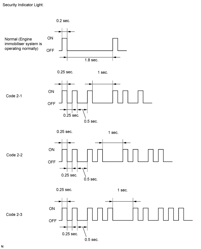
| Procedure | Security Indicator Light Condition |
| 1. Start registration. | Security indicator light is blinking. |
| 2. Insert one of master keys into the ignition key cylinder. | Security indicator light turned on. |
| 3. Select following items on the tester: (1) Body (2) Immobiliser (3) ID Utility (4) Immobiliser Code Registration
| Security indicator light turned off for 1 sec. and then turned on. |
| 4. Remove the key. | Security indicator light turned on.
|
| 5. Register another key? YES: Go to step 6. NO: Go to step 7.
| |
| 6. Insert another key into the ignition key cylinder. Then go to step 4. | Security indicator light turned off for 1 sec. and then turned on. |
| 7. End of registration. | |
End the new key code registration mode (when not using Techstream)
Turn the ignition switch ON and OFF 5 times within 10 seconds using a master key that has already been registered.
End the new key code registration mode (when using Techstream)
Insert the key into the ignition key cylinder and turn the Techstream ON.
Follow the instructions on the Techstream screen to end the new key code registration mode.

| REGISTRATION OF ADDITIONAL KEY (PROCEDURE "A") |
Additional key code registration
| Procedure | Security Indicator Light Condition | Time (Completion of operation) |
| 1. Start registration. | Security indicator light is blinking. | - |
| 2. Insert an already registered master key into the ignition key cylinder, turn the ignition switch ON, and turn the tester ON. | Security indicator light turned off. | Within 120 sec. |
| 3. Select following items on the tester: (1) Body (2) Immobiliser (3) ID Utility (4) Immobiliser Code Registration | Security indicator light turned on. | |
| 4. Remove the master key and then push NEXT button on tester. | Security indicator light turned on. | Within 20 sec. of the instruction on the tester. |
| 5. Insert unregistered key into the ignition key cylinder. | Security indicator light is blinking.
| Within 10 sec. |
6. After 60 sec., key is registered.
| Security indicator light turned off. | - |
| 7. Remove the key. | Security indicator light is blinking. | |
| 8. Tester screen displays number of registered keys. | ||
| 9. Register another key? YES: Go to step 2. NO: Go to step 10. | ||
| 10. End of registration. | ||
| ERASURE OF KEY CODE (PROCEDURE "D") |
Erasure all key codes except master key
| Procedure | Security Indicator Light Condition | Time (Completion of operation) |
| 1. Start of erasure. | Security indicator light is blinking. | - |
| 2. Insert previously registered master key into ignition key cylinder and turn ignition switch ON. | Security indicator light turned off. | Within 120 sec. |
| 3. Select following items on the tester: (1) Body Electrical (2) Immobiliser (3) ID Utility (4) Immobiliser Code Erasure | Security indicator light turned on for 1 sec. then turned off. | |
4. Remove the master key.
| Security indicator light turned on. | Within 10 sec. of the instruction on the tester. |
| 5. End of erasure. | ||
Erasure all of key codes
| Procedure | Security Indicator Light Condition | Time (Completion of operation) |
| 1. Using TIS, confirm that user and vehicle match. | Security indicator light is blinking. | - |
| 2. Start of erasure. | Security indicator light is blinking. | - |
| 3. Insert previously registered master key or unregistered key into ignition key cylinder and turn ignition switch ON. | Security indicator light turned off. | Within 120 sec. |
| 4. Select following items on the tester: (1) Body Electrical (2) Immobiliser (3) ID Utility (4) Immobiliser Code Erasure | Security indicator light turned on for 1 sec. then turned off. | Within 15 min. |
| 5. Completion of erasure of all key codes is displayed. | Security indicator light turned on. | - |
| 6. End of erasure. | ||
| ECU - ECM COMMUNICATION ID REGISTRATION (PROCEDURE "C") |
After replacing the transponder key ECU

Register the key code(s) by following the new key code registration procedure (procedure "B").
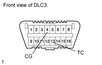
Using SST, connect terminals 13 (TC) and 4 (CG) of the DLC3 before inserting the key into the key cylinder.
| Procedure | Security Indicator Light Condition |
1. Insert previously registered key into ignition key cylinder and turn ignition switch ON.
| Security indicator light turned off. |
| 2. Leave vehicle as is for 30 min. | |
| 3. Turn the ignition switch OFF and disconnect terminals TC and CG. | |
| 4. Start engine. | |
| 5. Check that engine starts and stays on for more than 3 sec. Registration is complete. |
After replacing the ECM
Register the ECU - ECM communication ID.
| Procedure | Security Indicator Light Condition |
| 1. Insert previously registered key into ignition key cylinder. | Security indicator light turned off. |
| 2. Start engine. | |
| 3. Check that engine starts and stays on for more than 3 sec. Registration is complete. |
After replacing the transponder key ECU and ECM
Register the key code(s) by following the new key code registration procedure (procedure "B").
Register the ECU - ECM communication ID.
| Procedure | Security Indicator Light Condition |
| 1. Insert previously registered key into ignition key cylinder. | Security indicator light turned off. |
| 2. Start engine. | |
| 3. Check that engine starts and stays on for more than 3 sec. Registration is complete. |
| DESCRIPTION OF CODE REGISTRATION |
| REGISTER RECOGNITION CODE |
Turn the ignition switch ON.
Enter the following menus:
Select: Body / Main Body / Wireless Registration.
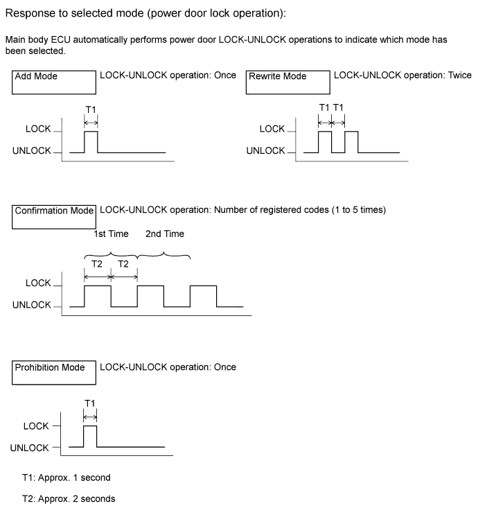
Press both LOCK and UNLOCK switches between 1 to 1.5 seconds.
Press either switch for more than 1 second within 3 seconds.
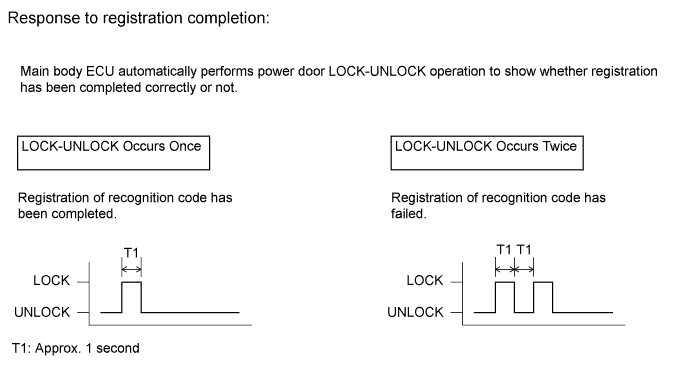
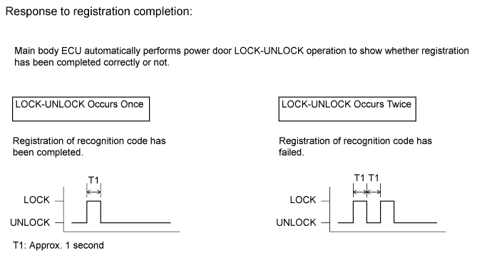
Check the response to the registration completion.

Perform either of the following to complete the registration of the recognition codes:
| REGISTER RECOGNITION CODE (USING SWITCH OPERATION) |
The following conditions must be met.
Insert and remove the key into / from the ignition key cylinder twice (Insert → Remove → Insert → Remove) within 5 seconds.
Perform the following operations within 40 seconds.
Close and open the driver side door twice (Close → Open → Close → Open).
Insert and remove the key into / from the ignition key cylinder (Insert → Remove).
Close and open the driver side door twice (Close → Open → Close → Open).
Insert the key into the ignition key cylinder and close all doors.
Perform the following operations within 40 seconds.
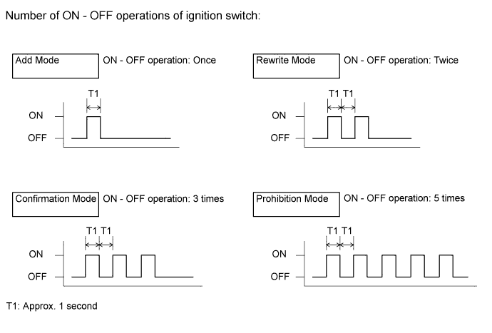
Turn the ignition switch from ON to OFF at approximately 1 second intervals. Operate the ignition switch according to the number of times shown below.

Remove the key from the ignition key cylinder.
Check the response of the selected mode within 5 seconds.

Press a single switch (LOCK or UNLOCK) within 5 seconds.
If add mode or rewrite mode is selected, perform the following procedures.
Press a single switch (LOCK or UNLOCK) within 5 seconds.
After completing the above step, check the response to the registration completion within 3 seconds.

| SELECT COMPASS DISPLAY MODE |
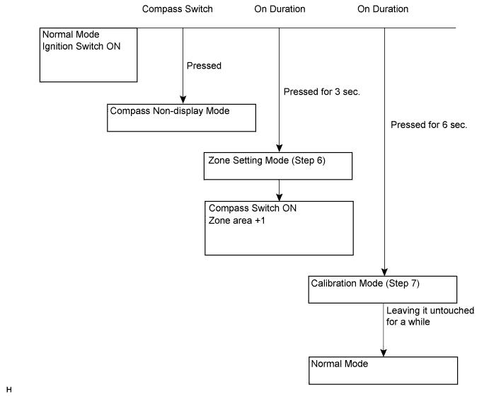
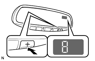
The compass switch allows you to select the Display or Non-display mode of the compass.
| SET ZONE |
Deviation between the "magnetic north" and "actual north" differs depending on the location. Therefore, adjustment of the magnetism is required. As the magnetic condition differs depending on the area where the vehicle is used, it is necessary for each user to set the zone (refer to Compass Zone Map). The zone setting can be changed using the compass switch of the inner mirror.
| PERFORM CALIBRATION |
As each vehicle has its own magnetic field, calibration should be performed for each individual vehicle. This compass function is used when storing the record of the vehicle's magnetic field.
| WHEN COMPASS IS MAGNETIZED |
A compass could be magnetized during shipping by vessels or freight cars. Therefore, make sure to perform calibration and ensure that calibration is performed properly before delivery. If this cannot be done (cannot be completed in spite of driving around several times), it may be caused by magnetization. Demagnetize the vehicle using a demagnetizer and perform calibration again.
| SET COMPASS |

| ZONE SETTING MODE |
![]() |
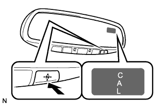
Pressing the compass switch for 3 seconds in the normal mode will activate the zone setting mode. A number (1 - 15) is displayed on the compass display.
The displayed number increases +1 every time the compass switch is pressed. Referring to the map, check the number for the area where the vehicle will be used and set the zone number.
Leave it untouched for several seconds after setting and check that the compass display shows an azimuthal direction (N, NE, E, SE, S, SW, W or NW) or "CAL".
| CALIBRATION SETTING MODE |
![]() |
Pressing the compass switch for 6 seconds in the normal mode will activate the calibration setting mode. "CAL" is displayed on the compass display.
Drive the vehicle at a slow speed of 8 km/h (5 mph) or less in a circular direction.
Driving in a circle 1 to 3 times will display the azimuthal direction on the display, completing the calibration.
The zone setting numbers are as follows:

| REGISTER TRANSMITTER CODE |
Reregister systems in the garage door opener registration mode.
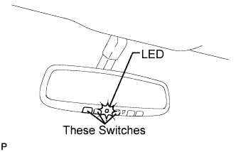
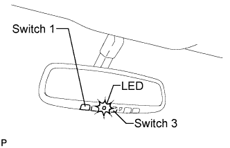
Select a garage door opener switch for transmitter code registration.
![]() |
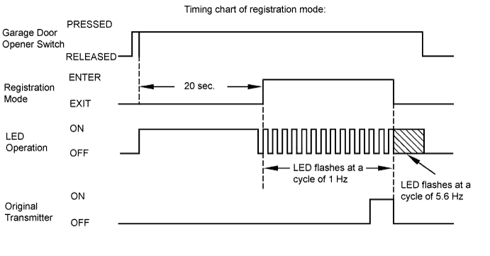
Press and hold the selected switch for 20 seconds. The garage door opener will enter registration mode.
![]() |
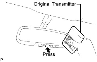
After the garage door opener has entered registration mode, bring the original transmitter of the system to be registered within 1 to 3 inches of the garage door opener and press and hold one of the garage door opener switches. Then press the original transmitter switch.
If the transmitter code registration was successful, the LED of the garage door opener flashes at a cycle of 5.6 Hz. If no malfunction occurs, release both the garage door opener switch and the original transmitter switch.

![]() |
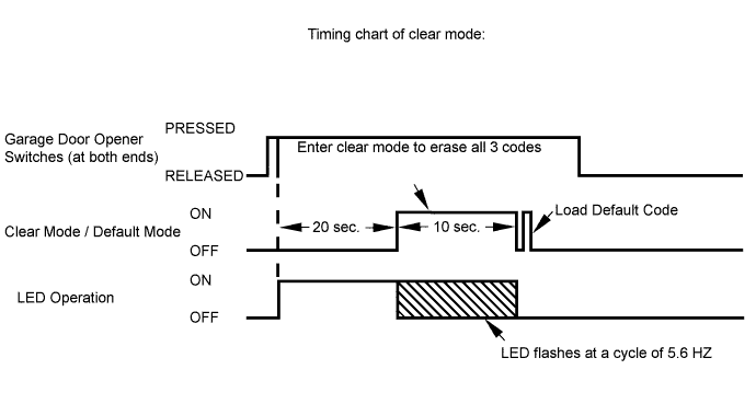
Erase transmitter codes in the garage door opener clear mode.
Press and hold the left and right switches of the garage door opener for 20 seconds. The LED will begin to flash at a cycle of 5.6 Hz. Releasing the switches will end clear mode.

Low power mode:
If a garage door opener switch is held for 100 seconds or more, the garage door opener will enter low power mode to economize on power consumption. When the garage door opener has entered low power mode, the LED turns off.
| INITIALIZE SLIDING ROOF DRIVE GEAR SUB-ASSEMBLY |
Turn the ignition switch ON.
If the sliding roof is open, close it fully.
By pushing the SLIDE switch to close or the TILT switch to up on the roof console box, make the sliding roof operate as follows: TILT UP → approximately 1 second → TILT DOWN → SLIDE OPEN → SLIDE CLOSE.
Check that the sliding roof stops at the fully closed position.
Finish the initialization.
Check that the AUTO operation works normally.