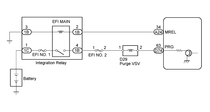
DTC P0443 Evaporative Emission Control System Purge Control Valve Circuit |
| DTC Code | DTC Detection Condition | Trouble Area |
| P0443 | Terminal voltage of ECM output circuit does not correspond with drive signals from ECM to purge VSV (1 trip detection logic) |
|
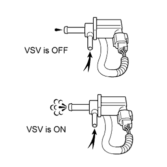
| 1.PERFORM ACTIVE TEST USING TECHSTREAM (ACTIVATE THE VSV FOR EVAP CONTROL) |
 |
Connect a Techstream to the DLC3.
Disconnect the vacuum hose (charcoal canister side) from the purge VSV.
Start the engine.
Turn the Techstream on.
Enter the following menus: Powertrain / Engine and ECT / Active Test / Activate the VSV for EVAP Control.
When the purge VSV is operated using the Techstream, check whether the port of the purge VSV applies suction to your finger.
| Tester Operation | Specified Condition |
| VSV ON | Purge VSV port applies suction to finger |
| VSV OFF | Purge VSV port applies no suction to finger |
|
| ||||
| OK | ||
 | ||
| ||
| 2.INSPECT PURGE VSV (RESISTANCE) |
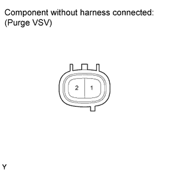 |
Disconnect the D29 purge VSV connector.
Measure the resistance according to the value(s) in the table below.
| Tester Connection | Condition | Specified Condition |
| 1 - 2 | 20°C (68°F) | 26 to 30 Ω |
|
| ||||
| OK | |
 |
| 3.INSPECT PURGE VSV (POWER SOURCE) |
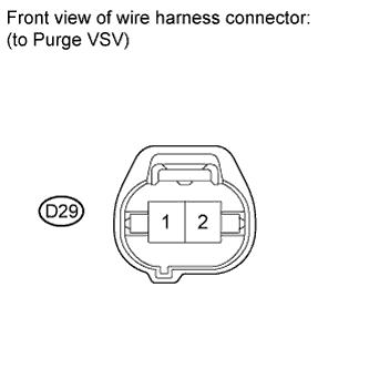 |
Disconnect the D29 purge VSV connector.
Turn the ignition switch to ON.
Measure the voltage according to the value(s) in the table below.
| Tester Connection | Switch Condition | Specified Condition |
| D29-1 - Body ground | Ignition switch ON | 11 to 14 V |
|
| ||||
| OK | |
|
| 4.CHECK HARNESS AND CONNECTOR (PURGE VSV - ECM) |
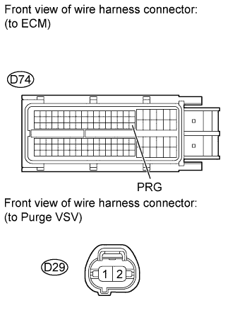 |
Disconnect the D29 purge VSV connector.
Disconnect the D74 ECM connector.
Measure the resistance according to the value(s) in the table below.
| Tester Connection | Condition | Specified Condition |
| D29-2 - D74-63 (PRG) | Always | Below 1 Ω |
| Tester Connection | Condition | Specified Condition |
| D29-2 or D74-63 (PRG) - Body ground | Always | 10 kΩ or higher |
|
| ||||
| OK | ||
| ||
| ||
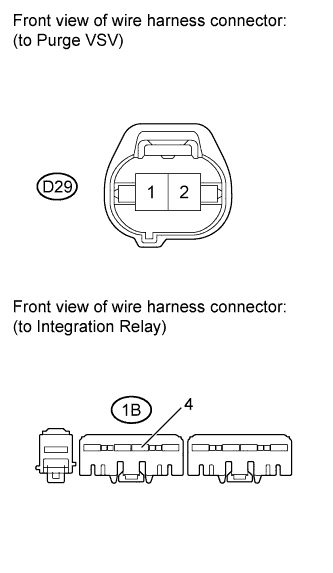
| 5.CHECK HARNESS AND CONNECTOR (PURGE VSV - INTEGRATION RELAY) |
 |
Check the EFI NO. 2 fuse.
Remove the EFI NO. 2 fuse from the engine room relay block.
Measure the resistance according to the value(s) in the table below.
| Tester Connection | Condition | Specified Condition |
| EFI No. 2 fuse | Always | Below 1 Ω |
Reinstall the EFI NO. 2 fuse.
Disconnect the D29 purge VSV connector.
Remove the integration relay from the engine room relay block.
Measure the resistance according to the value(s) in the table below.
| Tester Connection | Condition | Specified Condition |
| D29-1 - 1B-4 | Always | Below 1 Ω |
| D29-1 or 1B-4 - Body ground | Always | 10 kΩ or higher |
|
| ||||
| OK | ||
| ||
| ||

