 |
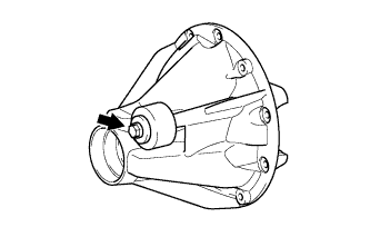
Install the dynamic and washer damper with the bolt.
- Torque:
- 17 N*m{ 168 kgf*cm , 12 ft.*lbf }
DIFFERENTIAL CARRIER ASSEMBLY (for 1GR-FE, 2UZ-FE) > REASSEMBLY |
| 1. INSTALL REAR DIFFERENTIAL DYNAMIC DAMPER (for Regular Cab Standard Deck) |
|
Install the dynamic and washer damper with the bolt.
| 2. INSTALL REAR DIFFERENTIAL DUST DEFLECTOR |
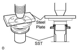 |
Using SST, a press and steel plate, press in the dust deflector.
| 3. INSTALL DIFFERENTIAL CASE ASSEMBLY |
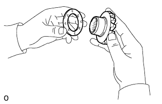 |
Install the 2 side gear thrust washers to the side gears.
Install the 2 side gears with the thrust washers, 2 pinion gears, 2 pinion gear thrust washers and pinion shaft.
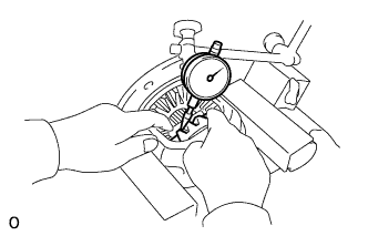 |
Using a dial indicator, measure the side gear backlash while holding one pinion gear toward the differential case.
| Thickness | Thickness |
| 1.53 to 1.57 mm (0.0602 to 0.0618 in.) | 1.78 to 1.82 mm (0.0701 to 0.0171 in.) |
| 1.58 to 1.62 mm (0.0622 to 0.0638 in.) | 1.83 to 1.87 mm (0.0720 to 0.0736 in.) |
| 1.63 to 1.67 mm (0.0642 to 0.0657 in.) | 1.88 to 1.92 mm (0.0740 to 0.0756 in.) |
| 1.68 to 1.72 mm (0.0661 to 0.0677 in.) | 1.93 to 1.97 mm (0.0760 to 0.0776 in.) |
| 1.73 to 1.77 mm (0.0681 to 0.0697 in.) | - |
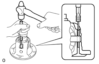 |
Using a pin punch and hammer, tap the straight pin through the holes in the differential case and pinion shaft.
Using a chisel and hammer, stake the outside of the differential case pin hole.
| 4. INSTALL REAR DIFFERENTIAL CASE BEARING |
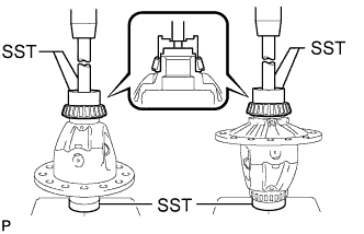 |
Using SST and a press, press in the 2 bearings.
| 5. INSTALL DIFFERENTIAL RING GEAR |
 |
Clean the contact surfaces of the differential case and ring gear.
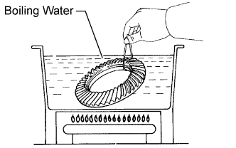
Heat the ring gear to approximately 100°C (212°F) in boiling water.
Carefully take the ring gear out of the boiling water.
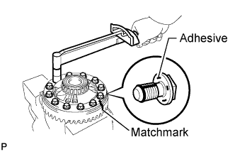 |
After the moisture on the ring gear has completely evaporated, quickly set the ring gear onto the differential case.
After the ring gear cools down sufficiently, apply adhesive to the bolts and install them.
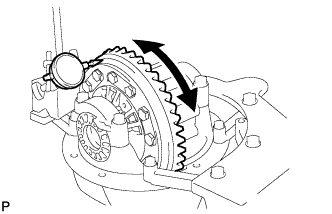
| 6. INSPECT DIFFERENTIAL RING GEAR RUNOUT |
 |
Install the differential case onto the carrier, and install the 2 adjusting nuts so that there is no play in the bearing.
Install the 2 bearing caps with the 4 bolts.
Install the 2 adjusting nut locks with the 2 bolts.
Using a dial indicator, measure the runout of the ring gear.
Remove the 2 bolts and adjusting nut locks.
Remove the 2 bearing caps, 2 adjusting nuts and differential case assembly.
| 7. INSTALL REAR DRIVE PINION FRONT TAPERED ROLLER BEARING |
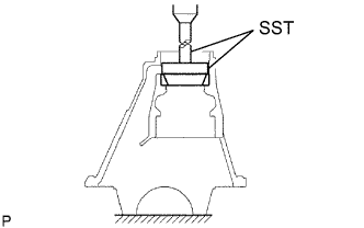 |
Using SST and a press, press in the bearing (outer race).
| 8. INSTALL REAR DRIVE PINION REAR TAPERED ROLLER BEARING |
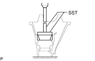 |
Using SST and a press, press in the bearing (outer race).
| 9. INSTALL REAR DRIVE PINION REAR TAPERED ROLLER BEARING |
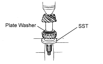 |
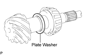
Install the plate washer onto the drive pinion.
Using SST and a press, press in the rear bearing (inner race).
| 10. INSPECT DIFFERENTIAL DRIVE PINION PRELOAD |
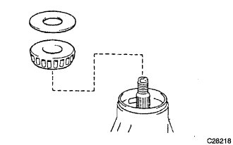 |
Install the drive pinion, front bearing (inner race) and oil slinger.
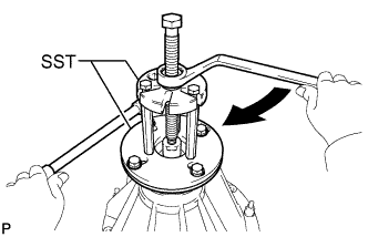 |
Using SST, install the companion flange.
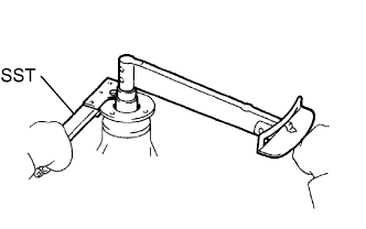 |
Using SST to hold the companion flange.
Coat the threads of the nut with hypoid gear oil.
Install the nut by tightening it until the standard preload is reached.
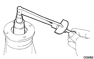 |
Using a torque wrench, measure the preload of the backlash between the drive pinion and ring gear.
| Bearing | Specified Condition |
| New | 1.04 to 1.69 N*m (11 to 17 kgf*cm, 10 to 14 in.*lbf) |
| Reused | 0.85 to 1.37 N*m (9 to 13 kgf*cm, 8 to 12 in.*lbf) |
| 11. INSTALL REAR DIFFERENTIAL CASE ASSEMBLY |
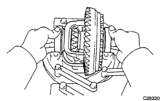 |
Place the 2 bearing outer races on their respective bearings.
| 12. INSTALL REAR DIFFERENTIAL BEARING ADJUSTING NUT |
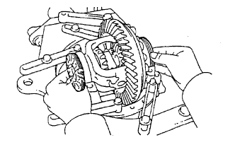 |
Install the 2 adjusting nuts onto the carrier, making sure the nuts are threaded properly.
| 13. INSPECT AND ADJUST DIFFERENTIAL RING GEAR AND DIFFERENTIAL DRIVE PINION BACKLASH |
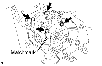 |
Align the matchmarks on the bearing cap and carrier.
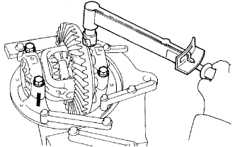 |
Install the right and left bearing caps with the 4 bolts.
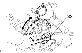 |
Loosen the 4 bearing cap bolts to the point where the adjusting nuts can be turned using SST.
Using SST, tighten the adjusting nut on the ring gear side until the ring has a backlash of about 0.2 mm (0.00788 in.).
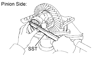 |
While turning the ring gear, use SST to tighten the adjusting nut on the drive pinion side. After the bearings have settled, loosen the adjusting nut on the drive pinion side.
Using SST, tighten the adjusting nut 1 to 1.5 notches from the 0 preload position.
|
Using a dial indicator, adjust the ring gear backlash until it is within the specification.
|
Tighten the bearing cap bolts.
| 14. INSPECT TOTAL PRELOAD |
|
Using a torque wrench, measure the preload with the teeth of the drive pinion and ring gear in contact.
| 15. INSPECT TOOTH CONTACT BETWEEN RING GEAR AND DRIVE PINION |
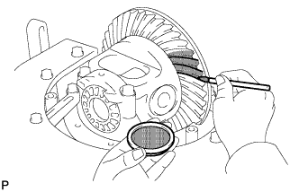 |
Coat 3 or 4 teeth at 3 different positions on the ring gear with Prussian blue.
Turn the companion flange in both directions to inspect the ring gear for proper tooth contact.
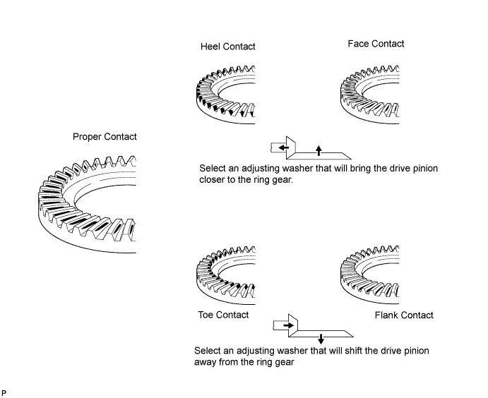
 |
| Thickness | Thickness |
| 1.04 to 1.06 mm (0.0409 to 0.0417 in.) | 1.315 to 1.335 mm (0.0518 to 0.0526 in.) |
| 1.065 to 1.085 mm (0.0420 to 0.0427 in.) | 1.34 to 1.36 mm (0.0528 to 0.0535 in.) |
| 1.09 to 1.11 mm (0.0419 to 0.0437 in.) | 1.365 to 1.385 mm (0.0537 to 0.0545 in.) |
| 1.115 to 1.135 mm (0.0439 to 0.0447 in.) | 1.39 to 1.41 mm (0.0547 to 0.0555 in.) |
| 1.14 to 1.16 mm (0.0449 to 0.0457 in.) | 1.415 to 1.435 mm (0.0558 to 0.0565 in.) |
| 1.165 to 1.185 mm (0.0459 to 0.0467 in.) | 1.44 to 1.46 mm (0.0567 to 0.0575 in.) |
| 1.19 to 1.21 mm (0.0469 to 0.0476 in.) | 1.465 to 1.485 mm (0.0577 to 0.0585 in.) |
| 1.215 to 1.235 mm (0.0478 to 0.0486 in.) | 1.49 to 1.51 mm (0.0587 to 0.0595 in.) |
| 1.24 to 1.26 mm (0.0488 to 0.0496 in.) | 1.515 to 1.535 mm (0.0597 to 0.0605 in.) |
| 1.265 to 1.285 mm (0.0498 to 0.0506 in.) | 1.54 to 1.56 mm (0.0607 to 0.0615 in.) |
| 1.29 to 1.31 mm (0.0508 to 0.0516 in.) | - |
| 16. REMOVE REAR DRIVE PINION NUT |
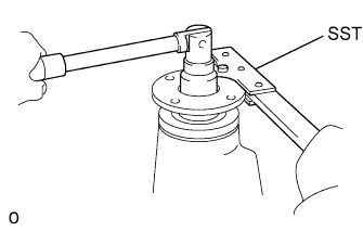 |
Using SST to hold the companion flange, remove the nut.
| 17. REMOVE REAR DRIVE PINION COMPANION FLANGE SUB-ASSEMBLY |
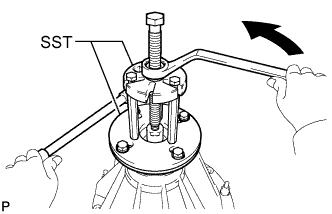 |
Using SST, remove the companion flange.
| 18. REMOVE REAR DIFFERENTIAL DRIVE PINION OIL SLINGER |
| 19. REMOVE REAR DRIVE PINION FRONT TAPERED ROLLER BEARING |
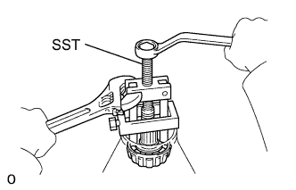 |
Using SST, remove the bearing (inner race).
| 20. INSTALL REAR DIFFERENTIAL DRIVE PINION BEARING SPACER |
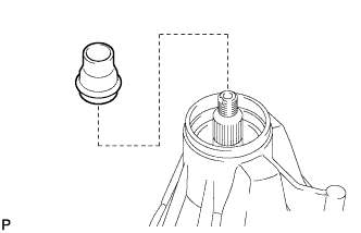 |
Install a new spacer onto the drive pinion.
| 21. INSTALL REAR DRIVE PINION FRONT TAPERED ROLLER BEARING |
|
Install the drive pinion, front bearing (inner race) and oil slinger.
|
Using SST and the companion flange, install the bearing (inner race) and then remove the companion flange.
| 22. INSTALL REAR DIFFERENTIAL CARRIER OIL SEAL |
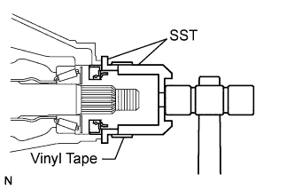 |
Using SST and a plastic-faced hammer, tap in a new oil seal until its surface is flush with the differential carrier end.
Coat the lip of the oil seal with MP grease.
| 23. INSTALL REAR DRIVE PINION COMPANION FLANGE SUB-ASSEMBLY |
|
Using SST, install the companion flange.
| 24. INSPECT DIFFERENTIAL DRIVE PINION PRELOAD |
Coat the threads of a new nut with hypoid gear oil.
|
Using SST to hold the companion flange.
Tighten the nut until the standard preload is reached.
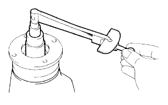 |
Using a torque wrench, measure the preload of the backlash between the drive pinion and ring gear.
| Bearing | Specified Condition |
| New | 1.04 to 1.69 N*m (11 to 17 kgf*cm, 10 to 14 in.*lbf) |
| Reused | 0.85 to 1.37 N*m (9 to 13 kgf*cm, 8 to 12 in.*lbf) |
| 25. INSPECT TOTAL PRELOAD |
|
Using a torque wrench, measure the preload with the teeth of the drive pinion and ring gear in contact.
| 26. INSPECT DIFFERENTIAL RING GEAR BACKLASH |
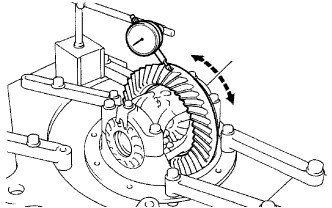 |
Using a dial indicator, check the backlash of the ring gear.
| 27. INSPECT RUNOUT OF REAR DRIVE PINION COMPANION FLANGE SUB-ASSEMBLY |
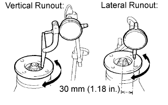 |
Using a dial indicator, measure the runout of the companion flange vertically and laterally.
| Runout | Specified Condition |
| Vertical runout | 0.09 mm (0.00355 in.) |
| Lateral runout | 0.09 mm (0.00355 in.) |
| 28. STAKE REAR DRIVE PINION NUT |
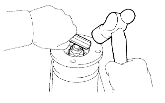 |
Using a chisel and hammer, stake the nut.
| 29. INSTALL REAR DIFFERENTIAL BEARING ADJUSTING NUT LOCK |
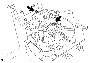 |
Install 2 new adjusting locks onto the bearing caps with the 2 bolts.
Bend the nut locks.