 |
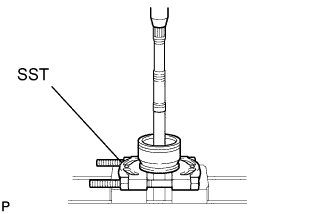
Using SST and a press, press in a new dust seal to the outboard joint shaft.
- SST
- 09950-00020
- NOTICE:
- Be careful not to damage the dust seal.
FRONT DRIVE SHAFT ASSEMBLY (for 4WD) > REASSEMBLY |
| 1. INSTALL DUST SEAL |
|
Using SST and a press, press in a new dust seal to the outboard joint shaft.
| 2. INSTALL FRONT DRIVE SHAFT DUST COVER LH |
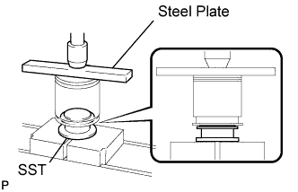 |
Using SST, a steel plate and press, press in a new dust cover.
| 3. INSTALL OUTBOARD JOINT BOOT |
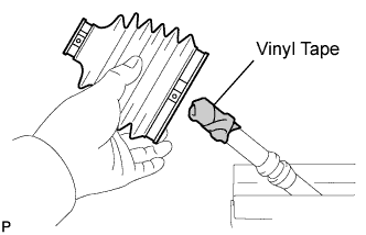 |
Place 2 new boot clamps on the boot.
Temporarily install a new boot to the outboard joint shaft.
Position the inside clamp onto the boot.
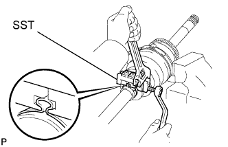 |
Using SST, pinch the inside clamp.
Pack the outboard joint and boot with grease in the boot kit.
Position the outside clamp onto the boot.
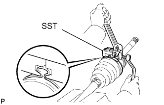 |
Using SST, pinch the outside clamp.
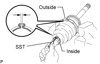 |
Using SST, adjust the clearance of the clamps.
| Clamp | Specified Condition |
| Inside | 2.8 to 3.8 mm (0.110 to 0.150 in.) |
| Outside | 3.5 to 4.5 mm (0.138 to 0.177 in.) |
| 4. TEMPORARILY INSTALL INBOARD JOINT BOOT |
Temporarily install 2 new boot clamps and a boot to the outboard joint shaft.
| 5. INSTALL INBOARD JOINT SHAFT |
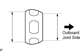 |
Install the cage to the outboard joint shaft.
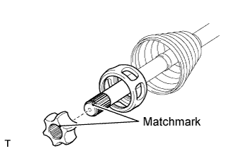 |
Align the matchmarks placed before removal.
Install the inner race.
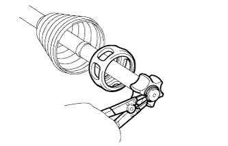 |
Using a snap ring expander, install a new snap ring.
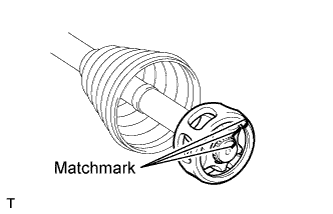 |
Align the matchmarks placed before removal, and install the cage to the inner race.
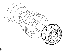 |
Install the 6 balls.
Pack the inboard joint shaft and boot with grease in the boot kit.
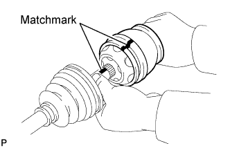 |
Align the matchmarks placed before removal, and install the inboard joint shaft to the outboard joint shaft.
Install a new snap ring.
Temporarily install the boot to the inboard joint shaft.
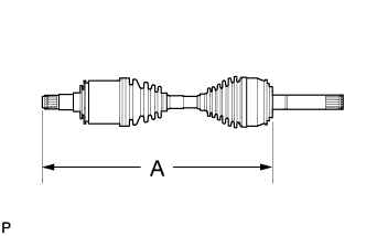 |
Check that the 2 boots are not stretched or contracted when the drive shaft is at standard length.
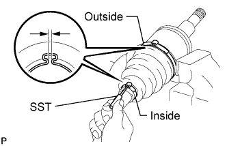 |
Install the inboard joint boot clamps in the same manner as the outboard side.
| Clamp | Specified Condition |
| Inside | 2.8 to 3.8 mm (0.110 to 0.150 in.) |
| Outside | 3.0 to 4.0 mm (0.118 to 0.158 in.) |
| 6. INSPECT FRONT DRIVE SHAFT ASSEMBLY |
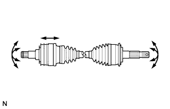 |
Check if there is excessive play in the outboard joint.
Check if the inboard joint shaft slides smoothly in the thrust direction.
Check if there is excessive play in the radial direction of the inboard joint shaft.
Check the boots for damage.