Home › BRAKE › BRAKE › REAR BRAKE

REAR BRAKE > INSTALLATION

for Preparation Click here


HINT:
  1. Use the same procedures for the LH side and RH side.
  2. The procedures listed below are for the LH side.


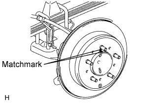
1. INSTALL REAR DISC


    C155452E01
  1. Align the matchmarks and install the rear disc.


2. ADJUST PARKING BRAKE SHOE CLEARANCE
  1. Temporarily install the hub nuts.

  1. Remove the hole plug.


    C158874E01
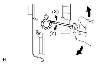
  1. Insert an adjustment tool into the adjustment hole of the disc. Rotate the adjustment wheel in the "X" direction until the shoes are locked. Then rotate the adjustment wheel in the "Y" direction 8 notches.

  1. Check that the disc can be rotated smoothly. If not, rotate the adjustment wheel in the "Y" direction and check again.

  1. Install the hole plug.

  1. Remove the hub nuts.


3. INSTALL REAR DISC BRAKE CYLINDER MOUNTING LH


    C193370E01
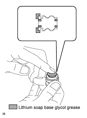
  1. Apply a light layer of lithium soap base glycol grease to the entire circumference of a new rear disc brake bush dust boot where it contacts the rear disc brake mounting cylinder, and the entire inner circumference of both ends.
    NOTICE:
    Apply a sufficient amount of lithium soap base glycol grease to the entire circumference of the rear disc brake bush dust boot and rear disc brake cylinder mounting contact surfaces.

    HINT:
    Apply at least 0.3 g (0.01 oz.) of lithium soap base glycol grease to each rear disc brake bush dust boot.


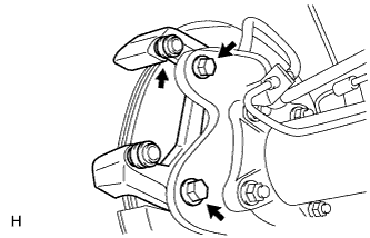
    C155444E03
  1. Install the boot to the rear disc brake cylinder mounting.

    NOTICE:
    Install the boot securely into the grooves of the rear disc brake cylinder mounting.

  1. Install the rear disc brake cylinder mounting with the 2 bolts.

    Torque:
    95 N*m{ 969 kgf*cm , 70 ft.*lbf }


4. INSTALL REAR DISC BRAKE PAD SUPPORT PLATE

NOTICE:
  1. The pad support plates can be reused if they are securely attached to the cylinder mounting. Therefore, do not remove the pad support plates from the cylinder mounting.
  2. If a pad support plate is removed, replace it with a new one that is supplied with double-sided tape already attached.
  3. Make sure to clean the cylinder mounting contact surface before attaching the pad support plates.

  1. Clean the cylinder mounting surface where the pad support plates will be attached.

  1. Remove the peeling paper from the double-sided tape, and install 4 new pad support plates to the cylinder mounting.


5. INSTALL PAD WEAR INDICATOR PLATE
  1. Install the pad wear indicator plate to the inner disc brake pad.


6. INSTALL REAR DISC BRAKE ANTI-SQUEAL SHIM
  1. Install the anti-squeal shims to the each brake pads.

    NOTICE:
    There should be no oil or grease on the friction surfaces of the brake pads and rear disc.


7. INSTALL REAR DISC BRAKE PAD
  1. Install the 2 disc brake pads to the disc brake cylinder mounting.

    NOTICE:
    1. When installing the pads, make sure that the disc brake pad support plates are securely attached to the cylinder mounting. The pad support plates are attached to the cylinder mounting with double-sided tape.
    2. If a pad support plate is not securely attached to the cylinder mounting, replace it with a new one.


8. INSTALL REAR DISC BRAKE CYLINDER ASSEMBLY LH


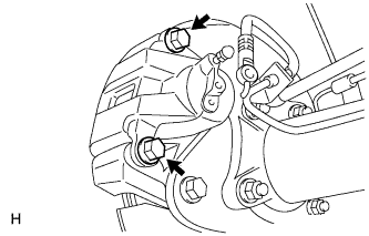
    C193405E01
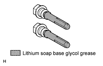
  1. Apply lithium soap base glycol grease to the sliding part and seal surface of the 2 slide pins.


    C155440
  1. Install the 2 slide pins.

    Torque:
    88 N*m{ 897 kgf*cm , 65 ft.*lbf }


9. CONNECT REAR FLEXIBLE HOSE LH


    C155439
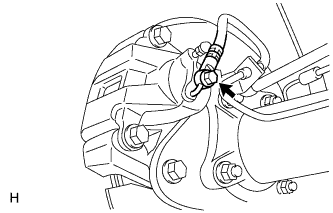
  1. Install a new gasket and connect the flexible hose with the union bolt.

    Torque:
    30 N*m{ 306 kgf*cm , 22 ft.*lbf }


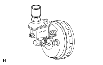
10. FILL RESERVOIR WITH BRAKE FLUID


    C155472
  1. Set the brake fluid can upside down on the reservoir.

    Fluid:
    SAE J1703 or FMVSS No. 116 DOT3

    NOTICE:
    1. Make sure there is sufficient brake fluid in the can.
    2. After adding brake fluid, make sure the reservoir is sufficiently full.


11. BLEED AIR FROM BRAKE MASTER CYLINDER

HINT:
If the master cylinder has been disassembled or if the reservoir becomes empty, bleed air from the master cylinder.


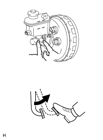
    C155473E02
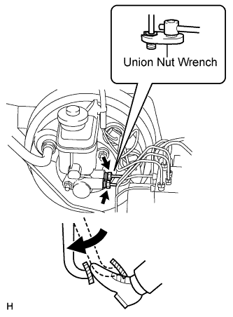
  1. Using a union nut wrench, disconnect the 2 brake lines from the master cylinder.

  1. Slowly depress and hold the brake pedal.


    C155474
  1. Block the outer holes with your fingers, and release the pedal.

  1. Repeat the 2 previous steps 3 or 4 times.

  1. Using a union nut wrench, connect the 2 brake lines to the master cylinder.

    Torque:
    without union nut wrench:
    20 N*m{ 199 kgf*cm , 14 ft.*lbf }
    with union nut wrench:
    18 N*m{ 185 kgf*cm , 13 ft.*lbf }

    HINT:
    1. This torque value can be obtained by using a torque wrench with a fulcrum length of 300 mm (11.8 in.) and a union nut wrench with a fulcrum length of 22 mm (0.866 in.) (Click here).
    2. The torque value for use with a union nut wrench is effective when the union nut wrench is parallel to the torque wrench.


12. BLEED AIR FROM BRAKE LINE


C155475E01

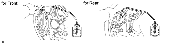
  1. Remove the bleeder plug cap.

  1. Connect the vinyl tube to the bleeder plug.

  1. Depress the brake pedal several times, and then loosen the bleeder plug with the pedal depressed.

  1. When fluid stops coming out, immediately tighten the bleeder plug. Then release the pedal.

  1. Repeat the 2 previous steps until all the air in the brake fluid is gone.

  1. Tighten the bleeder plug.

    Torque:
    11 N*m{ 110 kgf*cm , 8 ft.*lbf }

  1. Install the cap.

  1. Bleed air from the brake line for each wheel by repeating the above procedures.


13. BLEED AIR FROM VSC ACTUATOR ASSEMBLY

NOTICE:
After bleeding the air from the brake system, if the height or feel of the brake pedal cannot be obtained, perform air bleeding of the brake actuator with the Techstream by following the procedure below.

  1. Depress the brake pedal more than 20 times with the engine off.

  1. Connect the Techstream to the DLC3, and turn the ignition switch ON.

    NOTICE:
    Do not start the engine.

  1. Select AIR BLEEDING on the Techstream.

    HINT:
    Refer to the Techstream operator's manual for further details.

  1. Bleed the air out of the suction line.

    NOTICE:
    1. Perform the bleeding at the right front wheel and right rear wheel.
    2. Bleed the air by following the steps displayed on the Techstream.


    1. Connect a vinyl tube to the bleeder plug at the right front wheel or the right rear wheel.

    2. Loosen the bleeder plug.

    3. Operate the brake actuator to bleed the air using the Techstream.

      NOTICE:
      Release the brake pedal at this time.

      HINT:
      This operation stops automatically after 4 seconds.

    4. Check if the operation has stopped by referring to the Techstream display.

    5. Temporarily tighten the bleeder plug.

    6. Repeat the 4 previous steps until all air in the fluid is completely bled out.

    7. Tighten the bleeder plug.

      Torque:
      11 N*m{ 110 kgf*cm , 8 ft.*lbf }

    8. Repeat all of the above procedures for the other wheel to bleed the air out of the suction line.

  1. Bleed the air out of the pressure reduction line.

    NOTICE:
    1. Perform the bleeding at the 4 wheels.
    2. Bleed the air by following the steps displayed on the Techstream.


    1. Connect a vinyl tube to one of the bleeder plugs.

    2. Loosen the bleeder plug.

    3. Using the Techstream operate the brake actuator, completely depress the brake pedal and hold it there.

      NOTICE:
      1. During this procedure, the pedal will feel heavy, but completely depress it so that the brake fluid comes out of the bleeder plug.
      2. Depress and hold the brake pedal. Do not depress and release the pedal repeatedly.

      HINT:
      The operation stops automatically after 4 seconds. When performing this procedure continuously, set an interval of at least 20 seconds.

    4. Tighten the bleeder plug, then release the brake pedal.

    5. Repeat the 3 previous steps until all air in the fluid is completely bled out.

    6. Tighten the bleeder plug.

      Torque:
      11 N*m{ 110 kgf*cm , 8 ft.*lbf }

    7. Repeat all of the above procedures for the other wheels to bleed the air out of the pressure reduction line.


14. CHECK BRAKE FLUID LEVEL IN RESERVOIR


C155477
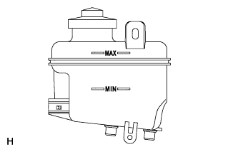
  1. Check the fluid level and add fluid if necessary.

    Fluid:
    SAE J1703 or FMVSS No. 116 DOT3

    HINT:
    Add fluid to a level between the reservoir's MIN and MAX lines.


15. CHECK FOR BRAKE FLUID LEAK


16. INSTALL REAR WHEEL

Torque:
for Aluminum Wheel:
131 N*m{ 1336 kgf*cm , 97 ft.*lbf }
for Steel Wheel:
209 N*m{ 2131 kgf*cm , 154 ft.*lbf }