 |
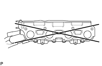
Using a precision straightedge and feeler gauge, measure the warpage of the contact surface of the cylinder head.
- Maximum warpage:
- 0.50 mm (0.0197 in.)
ENGINE UNIT > INSPECTION |
| 1. INSPECT EXHAUST MANIFOLD SUB-ASSEMBLY LH |
|
Using a precision straightedge and feeler gauge, measure the warpage of the contact surface of the cylinder head.
| 2. INSPECT EXHAUST MANIFOLD SUB-ASSEMBLY RH |
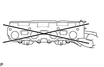 |
Using a precision straightedge and feeler gauge, measure the warpage of the contact surface of the cylinder head.
| 3. INSPECT CYLINDER HEAD SET BOLT |
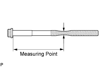 |
Using a vernier caliper, measure the thread outside diameter of the bolt.
| Item | Specified Condition |
| Intake side | 82 mm (3.23 in.) |
| Exhaust side | 86 mm (3.39 in.) |
| 4. INSPECT CAMSHAFT SUB-ASSEMBLY |
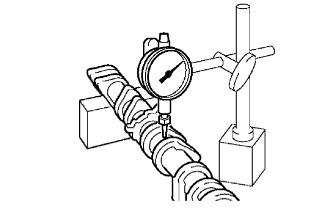 |
Inspect the circle runout.
Place the camshaft on V-blocks.
Using a dial indicator, measure the circle runout at the center journal.
 |
Inspect the cam lobes.
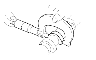
Using a micrometer, measure the cam lobe height.
| Item | Specified Condition |
| Intake | 42.61 to 42.71 mm (1.6776 to 1.6815 in.) |
| Exhaust | 42.63 to 42.73 mm (1.6783 to 1.6823 in.) |
| Item | Specified Condition |
| Intake | 42.46 mm (1.6717 in.) |
| Exhaust | 42.48 mm (1.6724 in.) |
Inspect the camshaft journals.
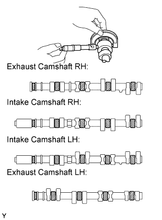 |
Using a micrometer, measure the journal diameter.
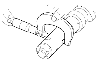 |
Using a micrometer, measure the journal diameter for the camshaft timing tube.
| 5. INSPECT CAMSHAFT TIMING TUBE ASSEMBLY |
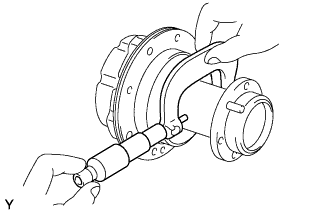 |
Using a micrometer, measure the journal diameter.
Install the camshaft timing tube to the camshaft .
Check the lock of the camshaft timing tube.
Check that the camshaft timing tube is locked.
 |
Release the lock pin.
Clean the camshaft timing tube journal with non-residue solvent.
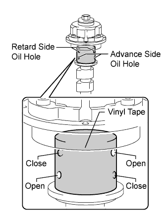
Wrap tape around the entire journal to block the 4 oil holes as shown in the illustration.
Open a hole in the tape at 2 places, one in the retard side oil hole and one in the advance side oil hole as shown in the illustration.
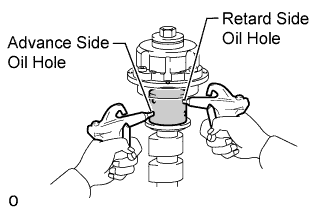 |
Apply approximately 200 kPa (2.0 kgf/cm2, 29 psi) of air pressure to the 2 open oil holes (the advance side oil hole and the retard side oil hole).
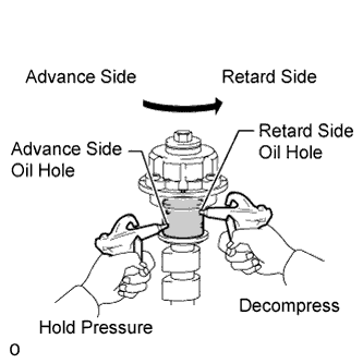 |
Check that the camshaft timing tube revolves in the advance direction when reducing the air pressure applied to the retard side oil hole.
When the camshaft timing tube reaches the most advanced position, release the air pressure from the retard side oil hole and advance side oil hole, in that order.
Check for smooth rotation.
Apply 60 kPa (0.6 kgf/cm2, 8.7 psi) of air pressure to the retard side oil hole to release the lock pin.
Turn the camshaft timing tube within its movable range (21°) 2 or 3 times, but do not turn it to the most retarded position. Make sure that the camshaft timing tube turns smoothly.
Check the lock in the most retarded position.
Confirm that the camshaft timing tube is locked at the most retarded position.
Remove the camshaft timing tube .
| 6. INSPECT CAMSHAFT GEAR SPRING |
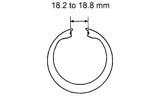 |
Using a vernier caliper, measure the gap distance of the gear spring.
| 7. INSPECT CAMSHAFT OIL CLEARANCE |
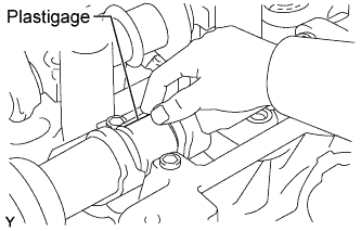 |
Clean the bearing caps and camshaft journals.
Check the bearings for flaking and scoring.
If the bearings are damaged, replace the cylinder head sub-assembly.
Place the camshafts on the cylinder head.
Lay a strip of Plastigage across each of the camshaft journals.
Install the bearing caps.
Remove the bearing caps.
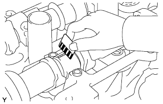 |
Measure the Plastigage at its widest point.
| Journal Position | Specified Condition |
| Camshaft journal | 0.030 to 0.071 mm (0.00118 to 0.00280 in.) |
| Camshaft timing tube journal | 0.036 to 0.057 mm (0.00141 to 0.00224 in.) |
| Journal Position | Specified Condition |
| Camshaft journal | 0.100 mm (0.00394 in.) |
| Camshaft timing tube journal | 0.075 mm (0.00295 in.) |
Remove the camshafts.
Completely remove the Plastigage.
| 8. INSPECT VALVE CLEARANCE |
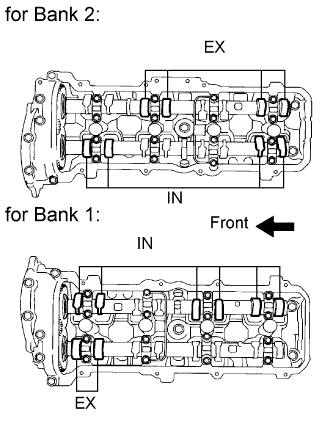 |
Check only the valves indicated.
Using a feeler gauge, measure the clearance between the valve lifter and camshaft.
| Item | Specified Condition |
| Intake | 0.15 to 0.25 mm (0.00591 to 0.00984 in.) |
| Exhaust | 0.25 to 0.35 mm (0.00984 to 0.0138 in.) |
Record the out-of-specification valve clearance measurements. They will be used later to determine the required replacement adjusting shim.
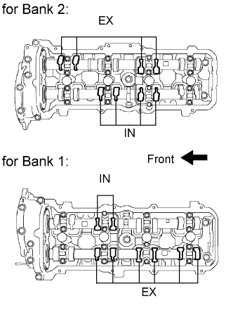 |
Turn the crankshaft 1 complete revolution (360°) and align the camshaft timing marks.
Check only the valves indicated in the illustration.
Using a feeler gauge, measure the clearance between the valve lifter and camshaft.
| Item | Specified Condition |
| Intake | 0.15 to 0.25 mm (0.00591 to 0.00984 in) |
| Exhaust | 0.25 to 0.35 mm (0.00984 to 0.0138 in.) |
Record the out-of-specification valve clearance measurements. They will be used later to determine the required replacement adjusting shim.
| 9. INSPECT TIMING BELT |
Visually check the timing belt for excessive wear, frayed cords, etc.
If necessary, replace the timing belt.
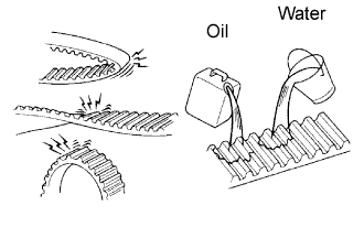 |
| 10. INSPECT TIMING BELT TENSIONER ASSEMBLY |
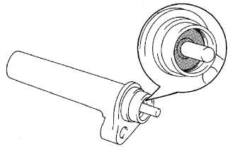 |
Visually check the seal portion of the tensioner for oil leakage.
If leakage is found, replace the tensioner.
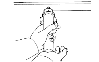 |
Hold the tensioner with both hands and push the push rod strongly as shown to check that it does not move.
If the push rod moves, replace the tensioner.
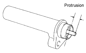 |
Measure the protrusion of the push rod from the housing end.
| 11. INSPECT NO. 1 TIMING BELT IDLER SUB-ASSEMBLY |
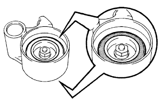 |
Visually check the seal portion of the idler for oil leakage.
If leakage is found, replace the idler.
Check that the idler turns smoothly.
If necessary, replace the idler.
| 12. INSPECT CYLINDER HEAD SUB-ASSEMBLY |
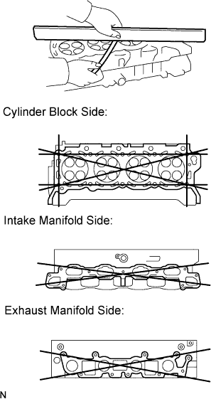 |
Using a precision straightedge and feeler gauge, measure the surfaces contacting the cylinder block and manifolds for warpage.
| Item | Specified Condition |
| Cylinder block side | 0.10 mm (0.00394 in.) |
| Intake manifold side | 0.10 mm (0.00394 in.) |
| Exhaust manifold side | 0.10 mm (0.00394 in.) |
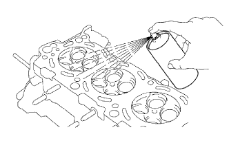 |
Using a dye penetrant, check the combustion chamber, intake ports, exhaust ports and cylinder block surface for cracks.
If the cylinder head is cracked, replace it.
| 13. INSPECT VALVE LIFTER |
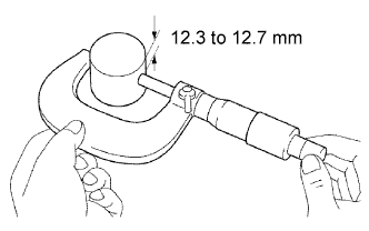 |
Using a micrometer, measure the lifter diameter at a position 12.3 to 12.7 mm (0.484 to 0.500 in.) from the top surface.
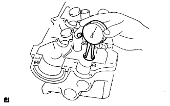 |
Using a caliper gauge, measure the lifter bore diameter of the cylinder head.
Subtract the lifter diameter measurement from the lifter bore diameter measurement.
| 14. INSPECT CAMSHAFT THRUST CLEARANCE |
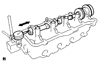 |
Inspect the clearance on the intake side.
Install the camshaft.
Using a dial indicator, measure the thrust clearance while moving the camshaft back and forth.
Remove the camshaft.
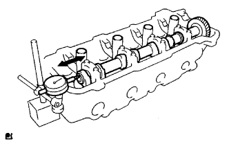 |
Inspect the clearance on the exhaust side.
Install the camshaft.
Using a dial indicator, measure the thrust clearance while moving the camshaft back and forth.
Remove the camshaft.
| 15. INSPECT CAMSHAFT GEAR BACKLASH |
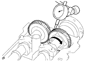 |
for Bank 1:
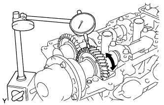
Install the No. 3 camshaft and No. 4 camshaft without installing the camshaft sub-gear and front bearing cap.
Using a dial indicator, measure the backlash.
Remove the No. 3 camshaft and No. 4 camshaft.
Remove the camshaft timing tube from the No. 3 camshaft.
Remove the drive gear from the camshaft timing tube.
 |
for Bank 2:
Install the No. 1 camshaft and No. 2 camshaft without installing the camshaft sub-gear and front bearing cap.
Using a dial indicator, measure the backlash.
Remove the No. 1 camshaft and No. 2 camshaft.
Remove the camshaft timing tube from the camshaft.
Remove the drive gear from the camshaft timing tube.
| 16. INSPECT CYLINDER BLOCK SUB-ASSEMBLY |
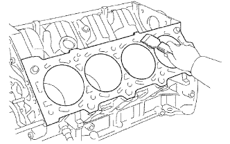 |
Clean the cylinder block.
Using a gasket scraper, remove all the gasket material from the top surface of the cylinder block.
Using a soft brush and solvent, thoroughly clean the cylinder block.
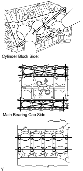 |
Using a precision straightedge and feeler gauge, measure the surfaces contacting the cylinder head and main bearing cap for warpage.
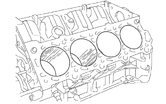 |
Visually check the cylinder for vertical scratches.
If deep scratches are present, rebore all 8 cylinders and replace all 8 pistons. If necessary, replace the cylinder block.