 |
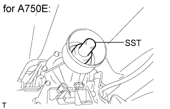
Remove SST from the transmission.
- SST
- 09325-40010
PROPELLER SHAFT ASSEMBLY (for 2WD) > INSTALLATION |
| 1. INSTALL PROPELLER SHAFT ASSEMBLY (for 2 Joint Type) |
|
Remove SST from the transmission.
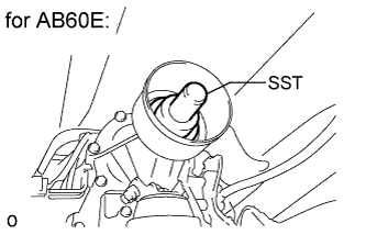 |
Remove SST from the transmission.
Insert the sleeve yoke into the transmission.
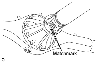 |
Align the matchmarks on the propeller shaft flange and differential flange.
Connect the propeller shaft to the differential side, and install the 4 bolts and 4 nuts.
| 2. MEASURE EXTENSION HOUSING AND DIFFERENTIAL FLANGE ANGLE (for 3 Joint Type) |
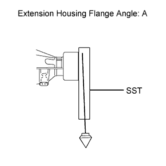 |
Using SST, measure and record the angle of the extension housing flange (A).
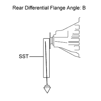 |
Using SST, measure and record the angle of the rear differential flange (B).
| 3. TEMPORARILY INSTALL PROPELLER WITH CENTER BEARING SHAFT ASSEMBLY (for 3 Joint Type) |
|
Remove SST from the transmission.
|
Remove SST from the transmission.
Insert the sleeve yoke into the transmission.
w/o Bearing Washer:
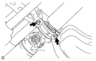 |
Temporarily install the center support bearing to the crossmember with the 2 mounting bolts.
w/ Bearing Washer:
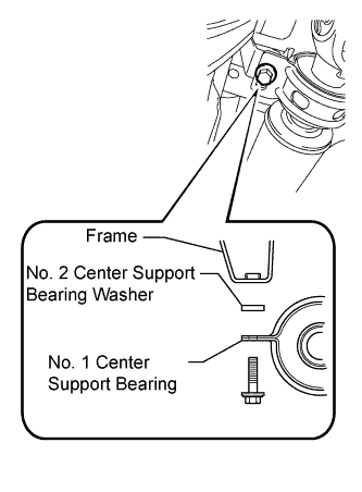 |
Temporarily install the center support bearing to the crossmember with the 2 bearing washers and 2 mounting bolts.
|
Align the matchmarks on the propeller shaft flange and differential flange.
Connect the propeller shaft to the differential side, and install the 4 bolts and 4 nuts.
| 4. TIGHTEN PROPELLER WITH CENTER BEARING SHAFT ASSEMBLY (for 3 Joint Type) |
With the vehicle empty and all 4 tires supported by a lift, or with the vehicle suspension in the full rebound position, adjust the center bearing so that dimension A (the distance from the front surface of the center bearing housing to the back surface of the intermediate shaft) is as shown in the chart below.
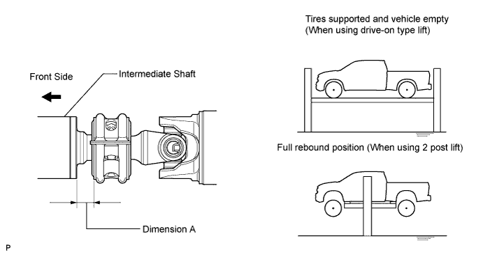
| Vehicle model | Dimension A | |
| Tires supported and vehicle empty (When using drive-on type lift) | Full rebound position (When using 2 post lift) | |
| GSK51L-CRASKA | 23.0 mm (0.906 in.) | 16.0 mm (0.630 in.) |
| GSK51L-THADKA | ||
| GSK51L-THADKA*1 | 19.0 mm(0.748 in) | |
| UCK51L-CRALKA*2 | 24.0mm (0.945 in.) | |
| UCK51L-CRASKA*2 | ||
| UCK51L-THADKA | 22.0mm (0.866 in.) | |
| UCK51L-THADKA*1 | 19.0 mm(0.748 in) | |
| UCK52L-CHASKA | 22.0mm (0.866 in.) | |
| USK51L-CRTLKA*2 | 23.0 mm (0.906 in.) | |
| USK51L-CRTSKA*2 | ||
| USK51L-THTDKA | 21.0 mm (0.827 in.) | |
| USK52L-CHTSKA | ||
| UCK51L-PSASKA*2 | 24.0 mm (0.945 in.) | |
| UCK51L-PSALKA*2 | ||
| USK51L-PSTSKA*2 | ||
| USK51L-PSTLKA*2 | ||
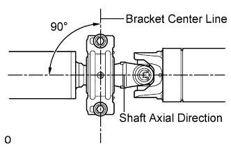 |
Check that the center line of the bracket is at right angles to the shaft axial direction.
Tighten the 2 mounting bolts.
| 5. INSPECT PROPELLER SHAFT ANGLE (for 3 Joint Type) |
Measure the No. 1 joint angle.
Using SST, measure and record the angle of the intermediate shaft (C).
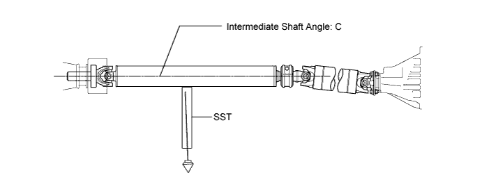
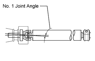 |
Subtract the angle of the extension housing flange (A) measured before installing the propeller shaft from the angle of the intermediate shaft (C) to calculate the No. 1 joint angle.
| Intermediate Shaft Angle Measured Value (C) | Extension Housing Flange Angle Measured Value (A) | No. 1 Joint Angle (Calculated Value) (C) - (A) |
| 3°15' (3.25°) | 4°00' (4.00°) | -0°45' (-0.75°) |
| Vehicle model | No. 1 joint angle |
| GSK51L-THADKA | -0°02' +/-0°60' (-0.03° +/-1.00°) |
| GSK51L-THADKA*1 | -0°47' +/-0°60' (-0.78° +/-1.00°) |
| UCK51L-THADKA | 0°41' +/-0°60' (0.68° +/-1.00°) |
| UCK51L-THADKA*1 | -0°05' +/-0°60' (-0.08° +/-1.00°) |
| USK51L-THTDKA | 0°41' +/-0°60' (0.68° +/-1.00°) |
| GSK51L-CRASKA | -0°02' +/-0°60' (-0.03° +/-1.00°) |
| UCK51L-CRASKA UCK51L-CRALKA | 0°41' +/-0°60' (0.68° +/-1.00°) |
| UCK51L-CRASKA*2 UCK51L-CRALKA*2 | 0°41' +/-0°60' (0.68° +/-1.00°) |
| UCK52L-CHASKA | 0°58' +/-0°60' (0.97° +/-1.00°) |
| USK51L-CRTSKA USK51L-CRTLKA | 0°41' +/-0°60' (0.68° +/-1.00°) |
| USK51L-CRTSKA*2 USK51L-CRTLKA*2 | 0°41' +/-0°60' (0.68° +/-1.00°) |
| USK52L-CHTSKA | 0°58' +/-0°60' (0.97° +/-1.00°) |
| UCK51L-PSASKA UCK51L-PSALKA | 0°41' +/-0°60' (0.68° +/-1.00°) |
| UCK51L-PSASKA*2 UCK51L-PSALKA*2 | 0°41' +/-0°60' (0.68° +/-1.00°) |
| USK51L-PSTSKA USK51L-PSTLKA | 0°41' +/-0°60' (0.68° +/-1.00°) |
| USK51L-PSTSKA*2 USK51L-PSTLKA*2 | 0°41' +/-0°60' (0.68° +/-1.00°) |
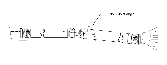
Measure the No. 2 joint angle.
Using SST, measure and record the angle of the propeller shaft (D).
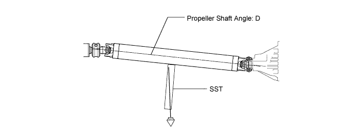
Subtract the angle of the propeller shaft (D) from the angle of the intermediate shaft (C) to calculate the No. 2 joint angle.
| Intermediate Shaft Angle Measured Value (C) | Propeller Shaft Angle Measured Value (D) | No. 2 Joint Angle (Calculated Value) (C) - (D) |
| 3°15' (3.25°) | 5°30' (5.50°) | -2°15' (-2.25°) |
| Vehicle model | No. 2 joint angle |
| GSK51L-THADKA | -1°28' +/-0°60' (-1.47° +/-1.00°) |
| GSK51L-THADKA*1 | -1°41' +/-0°60' (-1.68° +/-1.00°) |
| UCK51L-THADKA | -2°49' +/-0°60' (-2.82° +/-1.00°) |
| UCK51L-THADKA*1 | -2°14' +/-0°60' (-2.23° +/-1.00°) |
| USK51L-THTDKA | -2°43' +/-0°60' (-2.72° +/-1.00°) |
| GSK51L-CRASKA | -1°34' +/-0°60' (-1.57° +/-1.00°) |
| UCK51L-CRASKA UCK51L-CRALKA | -2°02' +/-0°60' (-2.03° +/-1.00°) |
| UCK51L-CRASKA*2 UCK51L-CRALKA*2 | -1°41' +/-0°60' (-1.68° +/-1.00°) |
| UCK52L-CHASKA | -1°20' +/-0°60' (-1.33° +/-1.00°) |
| USK51L-CRTSKA USK51L-CRTLKA | -2°02' +/-0°60' (-2.03° +/-1.00°) |
| USK51L-CRTSKA*2 USK51L-CRTLKA*2 | -1°47' +/-0°60' (-1.78° +/-1.00°) |
| USK52L-CHTSKA | -1°17' +/-0°60' (-1.28° +/-1.00°) |
| UCK51L-PSASKA UCK51L-PSALKA | -1°59' +/-0°60' (-1.98° +/-1.00°) |
| UCK51L-PSASKA*2 UCK51L-PSALKA*2 | -2°02' +/-0°60' (-2.03° +/-1.00°) |
| USK51L-PSTSKA USK51L-PSTLKA | -2°25' +/-0°60' (-2.42° +/-1.00°) |
| USK51L-PSTSKA*2 USK51L-PSTLKA*2 | -2°06' +/-0°60' (-2.10° +/-1.00°) |
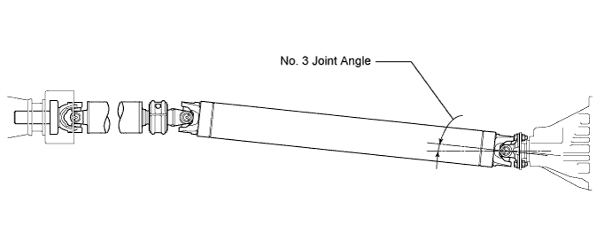
Measure the No. 3 joint angle.
Subtract the angle of the rear differential flange (B) measured before installing the propeller shaft from the angle of the propeller shaft (D) to calculate the No. 3 joint angle.
| Propeller Shaft Angle Measured Value (D) | Rear Differential Flange Angle Measured Value (B) | No. 3 Joint Angle (Calculated Value) (D) - (B) |
| 5°30' (5.50°) | 1°15' (1.25°) | 4°15' (4.25°) |
| Vehicle model | No. 3 joint angle |
| GSK51L-THADKA | 3°27' +/-0°60' (3.45° +/-1.00°) |
| GSK51L-THADKA*1 | 4°21' +/-0°60' (4.35° +/-1.00°) |
| UCK51L-THADKA | 4°04' +/-0°60' (4.07° +/-1.00°) |
| UCK51L-THADKA*1 | 4°13' +/-0°60' (4.22° +/-1.00°) |
| USK51L-THTDKA | 2°58' +/-0°60' (2.97° +/-1.00°) |
| GSK51L-CRASKA | 3°34' +/-0°60' (3.57° +/-1.00°) |
| UCK51L-CRASKA UCK51L-CRALKA | 3°19' +/-0°60' (3.32° +/-1.00°) |
| UCK51L-CRASKA*2 UCK51L-CRALKA*2 | 2°59' +/-0°60' (2.98° +/-1.00°) |
| UCK52L-CHASKA | 3°50' +/-0°60' (3.83° +/-1.00°) |
| USK51L-CRTSKA USK51L-CRTLKA | 2°50' +/-0°60' (2.83° +/-1.00°) |
| USK51L-CRTSKA*2 USK51L-CRTLKA*2 | 2°34' +/-0°60' (2.57° +/-1.00°) |
| USK52L-CHTSKA | 3°17' +/-0°60' (3.28° +/-1.00°) |
| UCK51L-PSASKA UCK51L-PSALKA | 3°47' +/-0°60' (3.78° +/-1.00°) |
| UCK51L-PSASKA*2 UCK51L-PSALKA*2 | 3°50' +/-0°60' (3.83° +/-1.00°) |
| USK51L-PSTSKA USK51L-PSTLKA | 4°12' +/-0°60' (4.20° +/-1.00°) |
| USK51L-PSTSKA*2 USK51L-PSTLKA*2 | 3°53' +/-0°60' (3.88° +/-1.00°) |
| 6. ADJUST PROPELLER SHAFT ANGLE (for 3 Joint Type) |
Adjust the No. 1, No. 2 and No. 3 joint angle.
Support the propeller shaft with a jack.
Remove the 2 center bearing mounting bolts.
Slowly lower the jack, and disconnect the center bearing.
Select an appropriate center support bearing washer thickness from the table below, and obtain a washer set.
| Thickness |
| 2.0 mm (0.0787 in.) |
| 4.5 mm (0.1772 in.) |
| 6.5 mm (0.2559 in.) |
| 9.0 mm (0.3543 in.) |
| 11.0 mm (0.4331 in.) |
| 13.5 mm (0.5315 in.) |
| 7. INSPECT FOR OIL LEAK |