 |
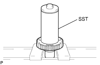
Using SST and a press, press in the drive clutch hub.
- SST
- 09513-36040
TRANSFER ASSEMBLY > REASSEMBLY |
| 1. INSTALL TRANSFER DRIVE CLUTCH HUB |
|
Using SST and a press, press in the drive clutch hub.
| 2. INSTALL FRONT DRIVE CLUTCH SLEEVE |
Apply gear oil to the connecting areas of the clutch sleeve and clutch hub.
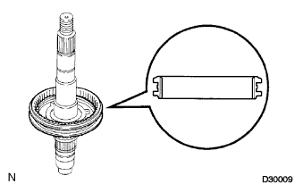 |
Install the drive clutch sleeve onto the rear output shaft.
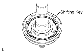 |
Install the 3 No. 1 synchromesh shifting keys and 2 No. 1 synchromesh shifting key springs.
| 3. INSTALL TRANSFER SYNCHRONIZER RING SET |
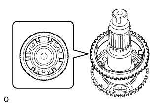 |
Install the outer synchronizer ring onto the rear output shaft.
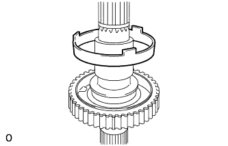 |
Install the center synchronizer ring onto the rear output shaft.
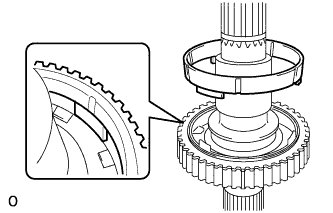 |
Install the inner synchronizer rings onto the rear output shaft.
| 4. INSTALL TRANSFER DRIVE SPROCKET SUB-ASSEMBLY |
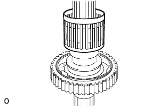 |
Install a new drive sprocket bearing.
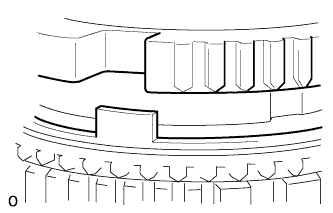 |
Install the drive sprocket.
| 5. INSTALL REAR TRANSFER OUTPUT SHAFT RADIAL BALL BEARING |
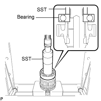 |
Using SST and a press, press in a new bearing.
| 6. INSPECT TRANSFER DRIVE SPROCKET SUB-ASSEMBLY |
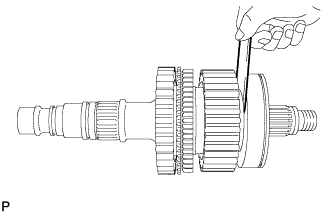 |
Using a feeler gauge, measure the drive sprocket thrust clearance.
| 7. INSTALL TRANSFER CLUTCH HUB |
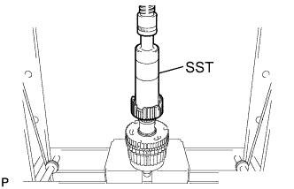 |
Using SST and a press, press in the clutch hub.
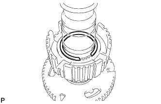 |
Select a snap ring that allows for minimum axial play and install it to the shaft.
| Mark | Thickness |
| B | 2.12 to 2.17 mm (0.0835 to 0.0854 in.) |
| C | 2.17 to 2.22 mm (0.0854 to 0.0874 in.) |
| D | 2.22 to 2.27 mm (0.0874 to 0.0894 in.) |
| E | 2.27 to 2.32 mm (0.0894 to 0.0913 in.) |
| F | 2.32 to 2.37 mm (0.0913 to 0.0933 in.) |
| G | 2.37 to 2.42 mm (0.0933 to 0.0953 in.) |
| H | 2.42 to 2.47 mm (0.0953 to 0.0974 in.) |
| J | 2.47 to 2.52 mm (0.0974 to 0.0992 in.) |
| K | 2.52 to 2.57 mm (0.0992 to 0.101 in.) |
Using a snap ring expander, install the snap ring.
| 8. INSTALL TRANSFER HIGH AND LOW CLUTCH SLEEVE |
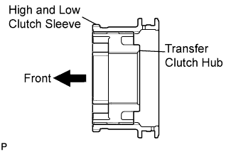 |
Install the high and low clutch sleeve onto the clutch hub.
| 9. INSTALL TRANSFER SYNCHROMESH SHIFTING KEY SPRING |
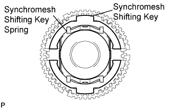 |
Install the synchromesh shifting key and synchromesh shifting key spring as shown in the illustration.
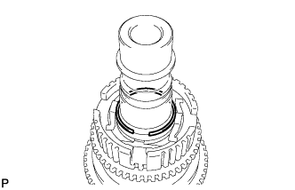 |
Using a snap ring expander, install the snap ring.
| 10. INSTALL NO. 1 TRANSFER OUTPUT SHAFT SPACER |
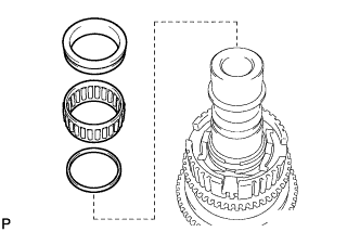 |
Install the washer, low planetary gear bearing and output shaft spacer to the output shaft.
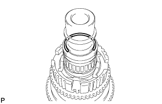 |
Using a snap ring expander, install the snap ring.
| 11. INSTALL TRANSFER CASE FRONT OIL SEAL |
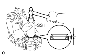 |
Using SST and a hammer, tap in a new oil seal until its surface is 1 to 1.5 mm (0.0394 to 0.0591 in.) from the front case upper surface.
Coat the lip of the oil seal with MP grease.
| 12. INSTALL TRANSFER DRIVEN SPROCKET BEARING |
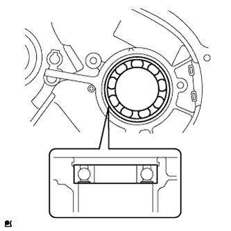 |
Install the bearing to the front case in the direction shown in the illustration.
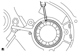 |
Using a screwdriver, install the snap ring.
| 13. INSTALL TRANSFER LOW PLANETARY RING GEAR |
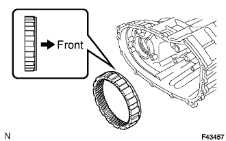 |
Install the ring gear to the transfer front case.
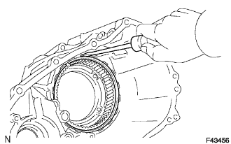 |
Using a screwdriver, install the snap ring.
| 14. INSTALL TRANSFER INPUT SHAFT PLUG |
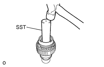 |
Using SST and a hammer, tap in a new input shaft plug.
| 15. INSTALL TRANSFER LOW PLANETARY GEAR ASSEMBLY |
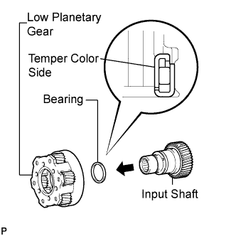 |
Install the low planetary gear bearing and low planetary gear to the input shaft.
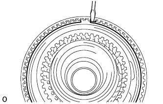 |
Using a screwdriver, install the low planetary gear spline piece.
| 16. INSTALL TRANSFER INPUT SHAFT BEARING |
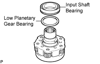 |
Install the input shaft bearing and low planetary gear bearing to the input shaft.
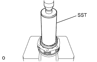 |
Using SST and a press, press in a new bearing.
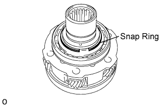 |
Select a snap ring that allows for minimum axial play and install it to the shaft.
| Mark | Thickness |
| C | 2.13 to 2.18 mm (0.0839 to 0.0858 in.) |
| D | 2.18 to 2.23 mm (0.0858 to 0.0878 in.) |
| E | 2.23 to 2.28 mm (0.0878 to 0.0898 in.) |
| F | 2.28 to 2.33 mm (0.0898 to 0.0917 in.) |
| G | 2.33 to 2.38 mm (0.0918 to 0.0937 in.) |
| H | 2.38 to 2.43 mm (0.0937 to 0.0957 in.) |
| J | 2.43 to 2.48 mm (0.0957 to 0.0976 in.) |
Using a snap ring expander, install the snap ring.
| 17. INSTALL NO. 1 TRANSFER INPUT SHAFT SEAL RING |
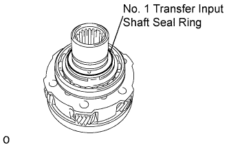 |
Install a new seal ring to the input shaft.
| 18. INSTALL TRANSFER OIL SEAL RING |
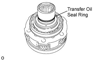 |
Install a new seal ring to the input shaft.
| 19. INSTALL INPUT SHAFT ASSEMBLY |
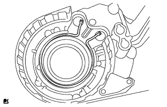 |
Install the snap ring to the front case.
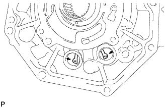 |
While expanding the snap ring, install the input shaft to the front case.
Apply adhesive to the threads of the 2 plugs.
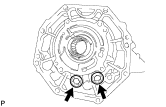 |
Install the 2 plugs.
| 20. INSTALL TRANSFER CASE MAGNET |
| 21. INSTALL TRANSFER OIL SEPARATOR SUB-ASSEMBLY |
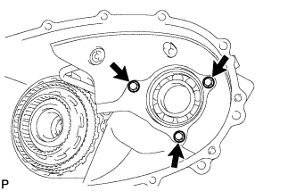 |
Install the oil separator with the 3 bolts.
| 22. INSTALL TRANSFER CASE REAR OIL SEAL |
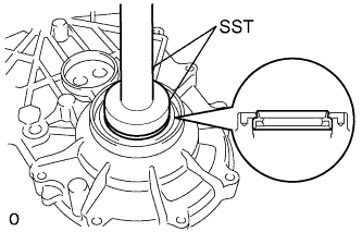 |
Using SST and a hammer, tap in a new oil seal until its surface is flush with the rear case upper surface.
Coat the lip of the oil seal with MP grease.
| 23. INSTALL SIDE GEAR SHAFT HOLDER BEARING |
Install the side gear shaft holder bearing to the rear case.
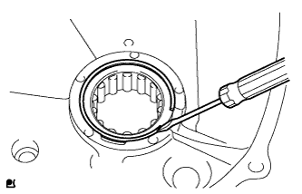 |
Using a screwdriver, install the snap ring.
| 24. INSTALL REAR OUTPUT SHAFT |
Install the snap ring to the rear case.
Mount the rear case in a vise.
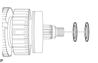 |
Install the output washer to the rear output shaft.
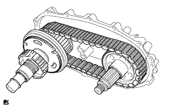 |
Install the rear output shaft , front drive chain and driven sprocket.
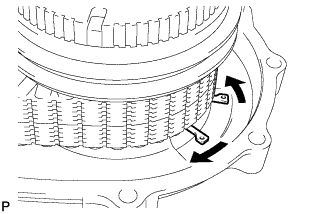 |
Using a snap ring expander, install the snap ring.
| 25. INSTALL TRANSFER SHIFT ACTUATOR ASSEMBLY |
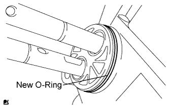 |
Install a new O-ring to the shift actuator.
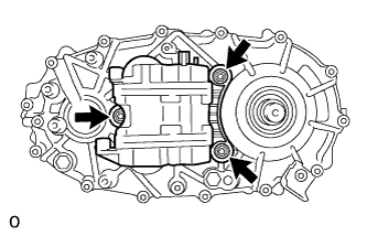 |
Set the No. 1 gear shift fork and No. 2 gear shift fork to the rear case. Then install the shift actuator to the rear case with the 3 bolts.
| 26. INSTALL NO. 1 TRANSFER GEAR SHIFT FORK |
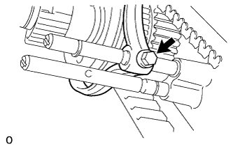 |
Install the No. 1 gear shift fork to the shift actuator with the bolt.
| 27. INSTALL NO. 2 TRANSFER GEAR SHIFT FORK |
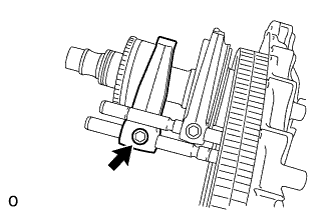 |
Install the No. 2 gear shift fork to the shift actuator with the bolt.
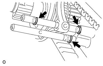 |
Using a screwdriver and hammer, tap the 3 shift fork shaft snap rings into the shift fork shaft.
| 28. INSTALL REAR TRANSFER CASE |
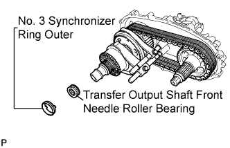 |
Install the output shaft front needle roller bearing and No. 3 synchronizer ring outer to the output shaft.
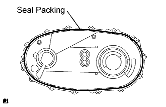 |
Apply seal packing to the rear case as shown in the illustration.
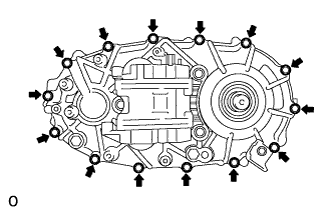 |
Install the rear case with the 14 bolts.
| 29. INSTALL TRANSFER CASE PLUG |
Apply adhesive to the threads of the plug.
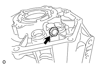 |
Install the plug.
| 30. INSTALL NO. 1 TRANSFER CASE PLUG |
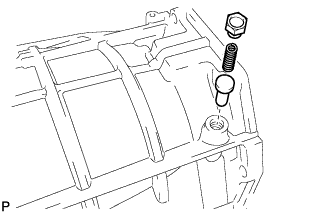 |
Install the pin and compression spring to the front case.
Apply adhesive to the threads of the plug.
Install the plug.
Apply adhesive to the threads of the plug.
| 31. INSTALL FRONT OUTPUT SHAFT COMPANION FLANGE SUB-ASSEMBLY |
Install the companion flange sub-assembly onto the drive sprocket sub-assembly.
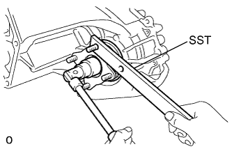 |
Using SST to hold the companion flange, install a new companion flange lock nut.
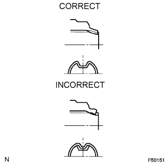 |
Using a chisel and hammer, stake the companion flange lock nut.
| 32. INSTALL REAR OUTPUT SHAFT COMPANION FLANGE SUB-ASSEMBLY |
Install the companion flange onto the output shaft.
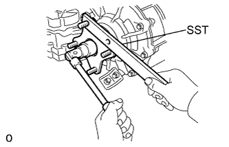 |
Using SST to hold the companion flange, install a new companion flange lock nut.
|
Using a chisel and hammer, stake the companion flange lock nut.
| 33. INSTALL TRANSFER OIL PUMP PLATE OIL SEAL |
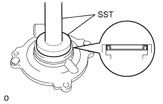 |
Using SST and a hammer, tap in a new oil seal until its surface is flush with the oil pump plate upper surface.
| 34. INSTALL TRANSFER CASE PLUG |
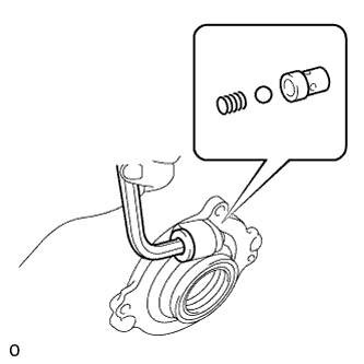 |
Install the relief valve seat, ball and compression ring to the oil pump plate.
Apply adhesive to the threads of the plug.
Using a 10 mm hexagon wrench, install the plug.
| 35. INSTALL TRANSFER CASE STRAIGHT PIN |
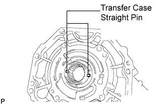 |
Install the straight pin to the input shaft.
| 36. INSTALL TRANSFER OIL PUMP PLATE |
Apply transfer oil to a new O-ring, drive rotor and driven rotor.
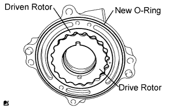 |
Install the O-ring, drive rotor and driven rotor to the oil pump plate.
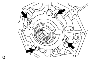 |
Install the oil pump plate with the 4 bolts.