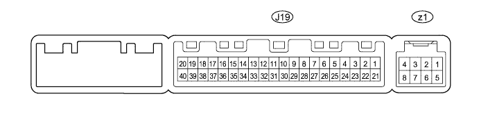
LIN COMMUNICATION SYSTEM > TERMINALS OF ECU |
| CHECK AIR CONDITIONING AMPLIFIER (A/C ECU) |
Measure the voltage and resistance according to the value(s) in the table below.
| Terminal No. (Symbols) | Wiring Color | Terminal Description | Condition | Specified Condition |
| J19-1 (IG+) - J19-14 (GND) | P - W-B | Ignition power supply | Ignition switch ON | 11 to 14 V |
| Ignition switch OFF | Below 1 V | |||
| J19-21 (B) - J19-14 (GND) | R - W-B | Battery power source | Always | 11 to 14 V |
| J19-14 (GND) - Body ground | W-B - Body ground | Ground | Always | Below 1 Ω |
| CHECK INTEGRATION CONTROL AND PANEL |

Disconnect the J37 integration control and panel connector.
Measure the voltage and resistance according to the value(s) in the table below.
| Terminal No. (Symbols) | Wiring Color | Terminal Description | Condition | Specified Condition |
| J37-16 (IG+) - J37-1 (GND) | P - W-B | Ignition power supply | Ignition switch ON | 11 to 14 V |
| Ignition switch OFF | Below 1 V | |||
| J37-1 (GND) - Body ground | W-B - Body ground | Ground | Always | Below 1 Ω |
| CHECK MAIN BODY ECU (DRIVER SIDE JUNCTION BLOCK) |
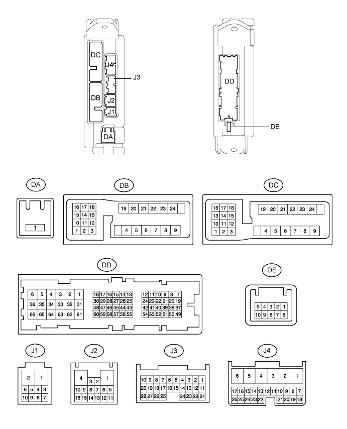
Disconnect the DA and DD ECU connectors.
Measure the voltage and resistance according to the value(s) in the table below.
| Terminal No. (Symbols) | Wiring Color | Terminal Description | Condition | Specified Condition |
| DA-1 (ACC) - Body ground | B - Body ground | ACC power supply | Always | 11 to 14 V |
| DA-1 (IG) - Body ground | B - Body ground | IG power supply | Always | 11 to 14 V |
| DD-62 (GND1)- Body ground | W-B - Body ground | Body ground | Always | Below 1 Ω |
| DD-62 (GND2) - Body ground | W-B - Body ground | Body ground | Always | Below 1 Ω |
| CHECK SLIDING ROOF DRIVE GEAR SUB-ASSEMBLY (SLIDING ROOF ECU) |

Disconnect the W3 ECU connector.
Measure the voltage and resistance according to the value(s) in the table below.
| Terminal No. (Symbols) | Wiring Color | Terminal Description | Condition | Specified Condition |
| W3-8 (E) - Body ground | W-B - Body ground | Ground | Always | Below 1 Ω |
| W3-9 (IG) - Body ground | SB - Body ground | IG power supply | Ignition switch ON | 11 to 14 V |
| Ignition switch OFF | Below 1 V | |||
| W3-10 (B) - Body ground | L - Body ground | +B power supply | Always | 11 to 14 V |