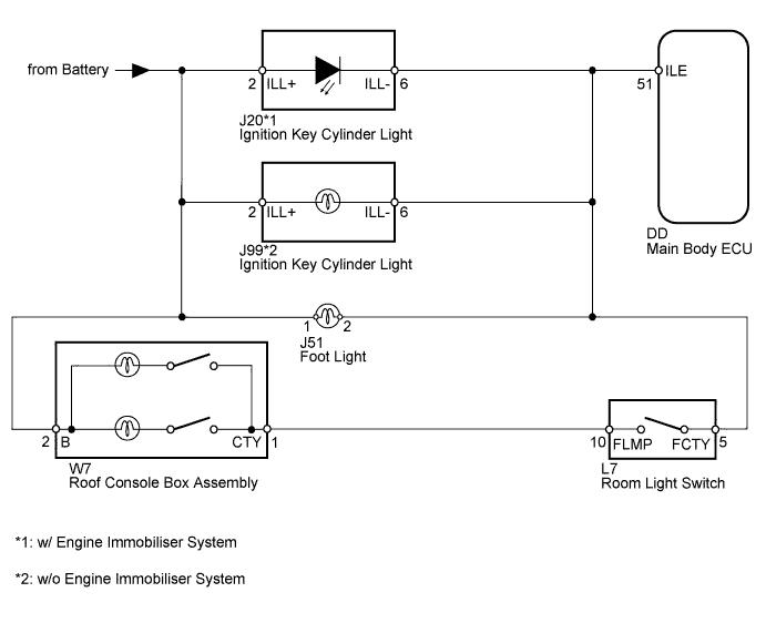
LIGHTING SYSTEM > Illumination Circuit |
| 1.PERFORM ACTIVE TEST USING TECHSTREAM (ILLUMINATION LIGHT) |
Operate the Techstream according to the steps on the display and select "Active Test".
| Tester Display | Test Part | Control Range | Diagnostic Note |
| Illumi Output | Illumination light | ON or OFF | - |
| Result | Proceed to |
| OK | A |
| NG (Only ignition key cylinder light does not turn on) | B |
| NG (Only foot light does not turn on) | C |
| NG (Only map light does not turn on) | D |
|
| ||||
|
| ||||
|
| ||||
| A | ||
 | ||
| ||
| 2.INSPECT IGNITION KEY CYLINDER LIGHT |
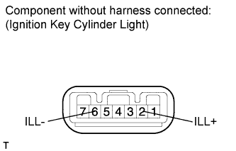 |
w/ Engine Immobiliser System:
Remove the ignition key cylinder light (Click here).
w/o Engine Immobiliser System:
Remove the ignition key cylinder light (Click here).
Connect the battery's positive (+) lead to terminal 2 (ILL+) and the negative (-) lead to terminal 6 (ILL-), and then check that the light turns on.
| Result | Proceed to |
| OK | A |
| NG (w/ Engine Immobiliser System) | B |
| NG (w/o Engine Immobiliser System) | C |
|
| ||||
|
| ||||
| A | |
 |
| 3.CHECK HARNESS AND CONNECTOR (IGNITION KEY CYLINDER LIGHT - MAIN BODY ECU AND BATTERY) |
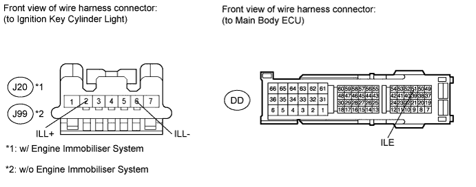
Disconnect the J20*1 or J99*2 light connector.
Disconnect the DD ECU connector.
Measure the voltage according to the value(s) in the table below.
| Tester Connection | Condition | Specified Condition |
| J20-2 (ILL+) - Body ground | Always | 11 to 14 V |
| Tester Connection | Condition | Specified Condition |
| J99-2 (ILL+) - Body ground | Always | 11 to 14 V |
Measure the resistance according to the value(s) in the table below.
| Tester Connection | Condition | Specified Condition |
| J20-6 (ILL-) - DD-51 (ILE) | Always | Below 1 Ω |
| J20-6 (ILL-) - Body ground | Always | 10 kΩ or higher |
| Tester Connection | Condition | Specified Condition |
| J99-6 (ILL-) - DD-51 (ILE) | Always | Below 1 Ω |
| J99-6 (ILL-) - Body ground | Always | 10 kΩ or higher |
|
| ||||
| OK | ||
| ||
| ||
| 4.INSPECT FOOT LIGHT |
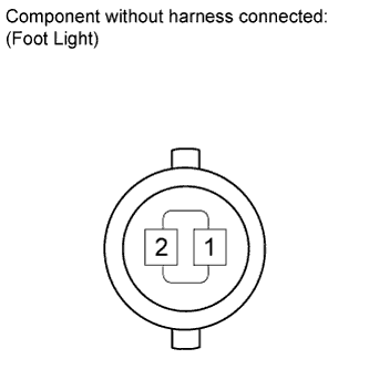 |
Remove the foot light (Click here).
Connect the battery's positive (+) lead to terminal 2 and the negative (-) lead to terminal 1, and then check that the light turns on.
|
| ||||
| OK | |
|
| 5.CHECK HARNESS AND CONNECTOR (FOOT LIGHT - MAIN BODY ECU AND BATTERY) |
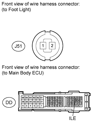 |
Disconnect the J51 light connector.
Disconnect the DD ECU connector.
Measure the voltage according to the value(s) in the table below.
| Tester Connection | Condition | Specified Condition |
| J51-1 - Body ground | Always | 11 to 14 V |
Measure the resistance according to the value(s) in the table below.
| Tester Connection | Condition | Specified Condition |
| J51-2 - DD-51 (ILE) | Always | Below 1 Ω |
| J51-2 - Body ground | Always | 10 kΩ or higher |
|
| ||||
| OK | ||
| ||
| ||
| 6.INSPECT ROOM LIGHT SWITCH |
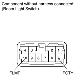 |
Remove the room light switch (Click here).
Measure the resistance according to the value(s) in the table below.
| Tester Connection | Switch Condition | Specified Condition |
| 5 (FCTY) - 10 (FLMP) | Room light switch DOOR | Below 1 Ω |
|
| ||||
| OK | |
|
| 7.INSPECT ROOF CONSOLE BOX ASSEMBLY |
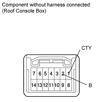 |
Remove the roof console box (Click here).
Roof console box switch is DOOR.
Connect the battery's positive (+) lead to terminal 2 (B) and the negative (-) lead to terminal 1 (CTY), and then check that the light turns on.
|
| ||||
| OK | |
|
| 8.CHECK HARNESS AND CONNECTOR (ROOF CONSOLE BOX - MAIN BODY ECU AND BATTERY) |
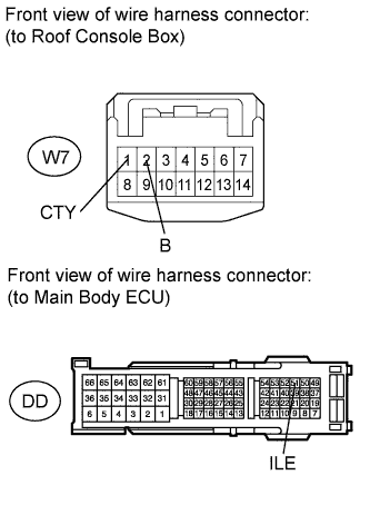 |
Disconnect the W7 box connector.
Disconnect the DD ECU connector.
Measure the voltage according to the value(s) in the table below.
| Tester Connection | Condition | Specified Condition |
| W7-2 (B) - Body ground | Always | 11 to 14 V |
Measure the resistance according to the value(s) in the table below.
| Tester Connection | Switch Condition | Specified Condition |
| W7-1 (CTY) - DD-51 (ILE) | Room light switch DOOR | Below 1 Ω |
| W7-1 (CTY) - Body ground | Room light switch DOOR | 10 kΩ or higher |
|
| ||||
| OK | ||
| ||
| ||

