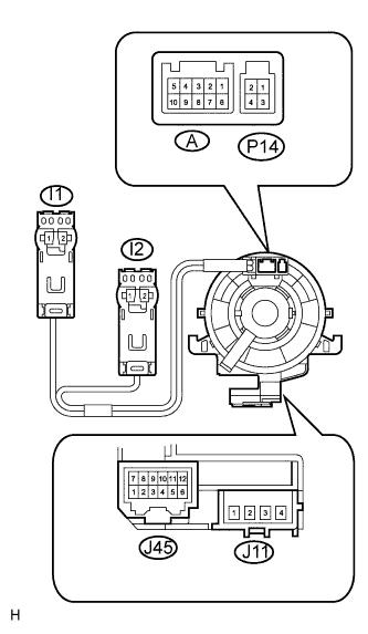
 |
Check the spiral cable.
Set the spiral cable to the center position (Click here).
After setting the spiral cable to the center position, rotate the spiral cable 2.5 times clockwise, and measure the resistance as shown. Then rotate the spiral cable 5 times counterclockwise, measure the resistance according to the U4 (uecs) in the table below.
- Standard resistance:
Tester Connection Condition Specified Condition J11-1 - I1-2 Always Below 1 Ω J11-2 - I1-1 J11-3 - I2-1 J11-4 - I2-2 J45-6 - A-10 J45-5 - A-9 J45-4 - A-8 J45-3 - A-7 J45-2 - A-6 J45-2 - P14-4 J45-1 - P14-3 J45-12 - A-5 J45-11 - A-4 J45-10 - A-3 J45-9 - A-2 J45-8 - A-1 J45-8 - P14-2 J45-7 - P14-1
After setting the spiral cable to the center position, rotate the spiral cable 2.5 times clockwise. Then while rotating the spiral cable 5 times counterclockwise, measure the resistance according to the U4 (uecs) in the table below.
- Standard resistance:
Tester Connection Condition Specified Condition J11-1 - I1-2 Always Below 1 Ω J11-2 - I1-1 J11-3 - I2-1 J11-4 - I2-2 J45-6 - A-10 J45-5 - A-9 J45-4 - A-8 J45-3 - A-7 J45-2 - A-6 J45-2 - P14-4 J45-1 - P14-3 J45-12 - A-5 J45-11 - A-4 J45-10 - A-3 J45-9 - A-2 J45-8 - A-1 J45-8 - P14-2 J45-7 - P14-1
- NOTICE:
- As the spiral cable may break, do not rotate the spiral cable more than the specified amount.