 |
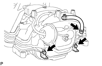
Install the tube hose to the intake manifold.
INTAKE MANIFOLD > INSTALLATION |
| 1. INSTALL UNION TO CONNECTOR TUBE HOSE |
|
Install the tube hose to the intake manifold.
Install the 2 wire harness brackets with the 2 bolts.
| 2. INSTALL PURGE VSV |
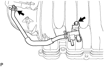 |
Connect the purge line hose to the intake manifold.
Install the purge VSV to the intake manifold with the bolt.
| 3. INSTALL VACUUM SWITCHING VALVE ASSEMBLY (for ACIS) |
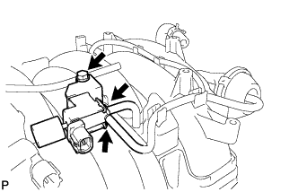 |
Install the vacuum switching valve to the intake manifold with the bolt.
Connect the 2 vacuum hoses to the vacuum switching valve.
| 4. INSTALL THROTTLE BODY ASSEMBLY |
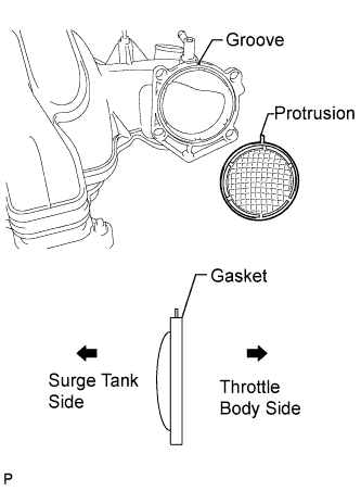 |
Align the protrusion of a new gasket with the groove of the intake manifold, and install the gasket.
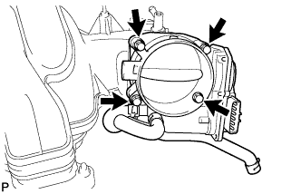 |
Install the throttle body with the 4 bolts.
| 5. INSTALL V-BANK COVER PIN |
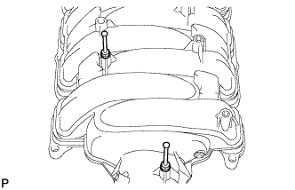 |
Install the 2 pins to the intake manifold.
| 6. INSTALL V-BANK COVER BRACKET |
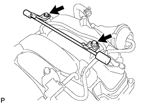 |
Install the bracket with the 2 bolts.
| 7. INSTALL VENTILATION HOSE ASSEMBLY |
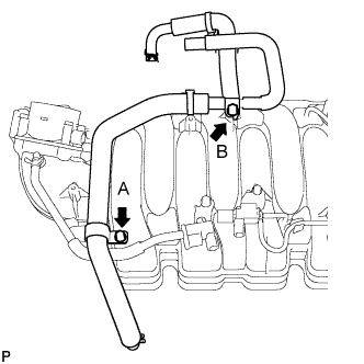 |
Install the ventilation hose to the intake manifold with the 2 bolts.
| 8. INSTALL INTAKE MANIFOLD |
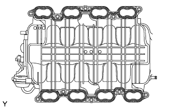 |
Place 2 new gaskets on the intake manifold.
Place the intake manifold on the cylinder head.
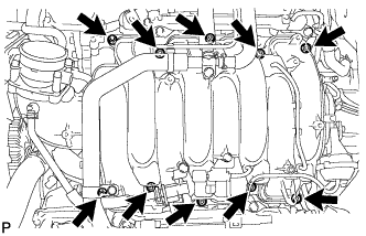 |
Install and uniformly tighten the 8 bolts and 2 nuts in several steps.
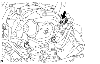 |
Install the wire bracket to the intake manifold with the bolt.
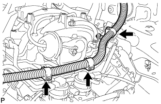 |
Connect the 3 wire clamps to the 3 wire brackets.
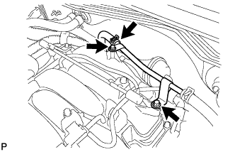 |
Connect the No. 1 tube and install it to the intake manifold with the 2 bolts.
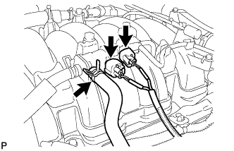 |
Connect the purge VSV connector.
Connect the purge line hose to the purge VSV.
Connect the vacuum switching valve connector (for ACIS).
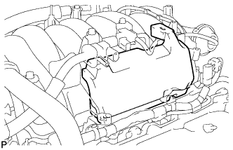 |
Install the No. 1 engine cover sub-assembly.
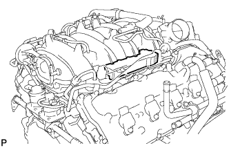 |
Install the No. 3 engine cover.
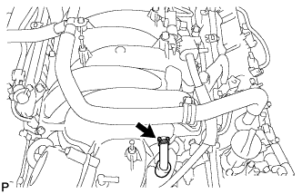 |
Connect the No. 1 ventilation hose.
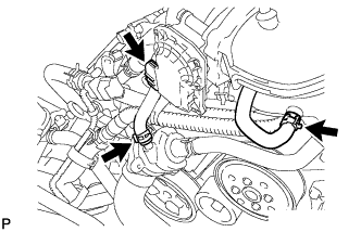 |
Connect the 2 water by-pass hoses.
Connect the throttle body connector.
| 9. CONNECT VENTILATION HOSE ASSEMBLY |
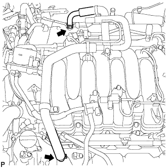 |
Connect the ventilation hose to the ventilation pipe of the cylinder head cover LH and RH.
| 10. INSTALL AIR CLEANER HOSE ASSEMBLY |
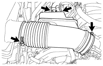 |
Install the air cleaner hose with the 2 clamps.
Connect the vacuum hose and ventilation hose.
| 11. INSTALL COWL TOP OUTER PANEL SUB-ASSEMBLY |
Install the outer panel with the 7 bolts.
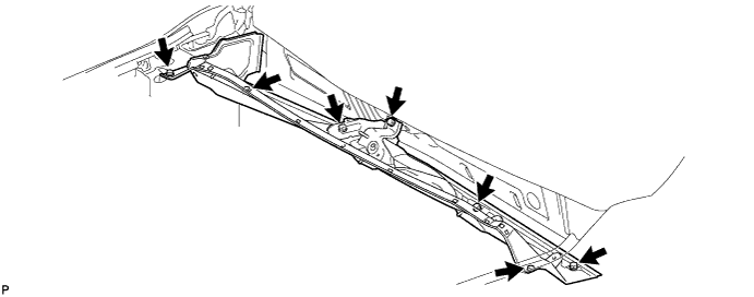
Connect the 2 washer hoses.
| 12. INSTALL FRONT WIPER MOTOR AND LINK ASSEMBLY |
Install the front wiper motor and link (Click here).
| 13. ADD ENGINE COOLANT |
Add engine coolant.
| Item | Specified Condition |
| w/ Trailer Towing System | 13.0 liters (13.7 US qts, 11.4 Imp. qts) |
| w/o Trailer Towing System | 12.1 liters (12.8 US qts, 10.6 Imp. qts) |
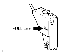 |
Slowly pour coolant into the radiator reservoir until it reaches the FULL line.
Install the reservoir cap.
Press the inlet and outlet radiator hoses several times by hand, and then check the coolant level. If the coolant level is low, add coolant.
Install the radiator cap.
Start the engine and warm it up until the thermostat opens.
Maintain the engine speed at 2000 to 2500 rpm.
Press the inlet and outlet radiator hoses several times by hand to bleed air.
Stop the engine, and wait until the engine coolant cools down to ambient temperature.
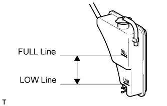 |
Check that the coolant level is between the FULL and LOW lines.
If the coolant level is below the LOW line, repeat all of the procedures above.
If the coolant level is above the FULL line, drain coolant so that the coolant level is between the FULL and LOW lines.
| 14. INSPECT FOR COOLANT LEAK |
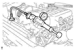 |
Fill the radiator with coolant and attach a radiator cap tester.
Warm up the engine.
Using the radiator cap tester, increase the pressure inside the radiator to 118 kPa (1.2 kgf/cm2, 17 psi), and check that the pressure does not drop.
If the pressure drops, check the hoses, radiator and water pump for leaks. If no external leaks are found, check the heater core, cylinder block and head.
| 15. INSTALL V-BANK COVER SUB-ASSEMBLY |
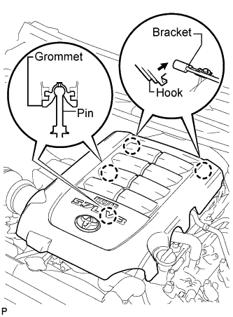 |
Attach the 2 V-bank cover hooks to the bracket. Then align the 2 V-bank cover grommets with the 2 pins, and press down on the V-bank cover to attach the pins.
| 16. INSTALL NO. 1 ENGINE UNDER COVER |
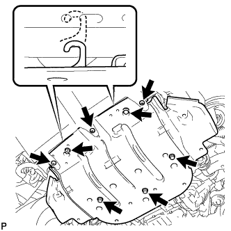 |
Hook the engine under cover to the vehicle body as shown in the illustration.
Install the 3 screws and 5 bolts.