Home › INTRODUCTION › INTRODUCTION › REPAIR INSTRUCTION

REPAIR INSTRUCTION > INITIALIZATION


PROCEDURES NECESSARY WHEN ECU OR OTHER PARTS ARE REPLACED

PROCEDURES NECESSARY WHEN ECU OR OTHER PARTS ARE REPLACED 
Replacement Part
Necessary Procedures
Effects / Inoperative Functions When Necessary Procedures are not Performed
Notes
for 1GR-FE:
  1. Throttle body with motor assembly
  2. Cleaning the deposits from the throttle body with motor assembly
  3. Engine assembly
  4. Cylinder head sub-assembly
  5. Camshaft (for intake or exhaust camshaft)
  6. Camshaft timing gear assembly
  7. Camshaft timing exhaust gear assembly
  8. Piston or piston ring
  9. Mass air flow meter sub-assembly
  10. Fuel injector assembly
  11. Fuel pump
  12. Air fuel ratio sensor
  13. Heated oxygen sensor
  14. Engine coolant temperature sensor
  15. Spark plug
  16. Ignition coil assembly
  17. Air leaks from intake system
  18. Gas leaks from exhaust system
  19. Knock control sensor
Initialization
Engine control system
-
ECM
Register VIN
DTC P0630 is output
-
Fuel with different alcohol concentration is used (for 3UR-FBE)
Reset fuel density learning value
  1. Engine starting
  2. Rough idling
-
  1. Automatic transmission assembly
  2. Valve body assembly
  3. Any of the shift solenoid valves
Reset memory
Large shift shock
-
Tire pressure warning ECU
  1. Register transmitter IDs
  2. Initialize tire pressure warning system
  1. When DTC detection conditions of "transmitter ID not received" DTC is met, tire pressure warning light blinks for 1 minute, and then illuminates
  2. Tire pressure monitoring function
-
Tire pressure warning valve and transmitter
  1. Register transmitter IDs
  2. Initialize tire pressure warning system
  1. When DTC detection conditions of "transmitter ID not received" DTC is met, tire pressure warning light blinks for 1 minute, and then illuminates
  2. Tire pressure monitoring function of replaced wheel
Even if only one wheel is replaced, IDs for all 4 wheels must be registered.
Skid control ECU
  1. Deceleration sensor zero point calibration
  2. Master cylinder pressure sensor zero point calibration
  1. ABS warning light illumination
  2. Slip indicator light illumination
-
Yaw rate sensor
  1. Zero point calibration data clearance
  2. Deceleration sensor zero point calibration
  1. ABS warning light illumination
  2. Slip indicator light illumination
  3. VSC control is prohibited or operation is incorrect
-
Front Wheel Alignment Adjustment
  1. Zero point calibration data clearance
  2. Deceleration sensor zero point calibration
  3. Perform initialization of steering angle sensor
  1. ABS warning light illumination
  2. Slip indicator light illumination
Complete the adjustment of the steering wheel and wheel alignment, and then initialize the steering angle sensor. If the order is reversed, the steering wheel and wheel alignment will become misaligned.
Occupant classification ECU
  1. Zero point calibration
  2. Sensitivity check
  1. Occupant classification system
  2. Passenger airbag ON/OFF indicator
  3. Airbag system (Front passenger side)
  4. Seat belt warning system (Front passenger side)
-
  1. Transponder key ECU
  2. ECM
  3. Key
Registration
Engine starting
-
  1. Door control transmitter
  2. Door control receiver
Register recognition code
Wireless door lock operation
-
  1. Power window regulator motor (Driver side)
  2. Power window regulator motor (Passenger side)
Initialize the motor
  1. Jam Protection Function
  2. Power window control system (w/ Jam protection function)
-
Inner rear view mirror
  1. Compass zone setting
  2. Compass calibration
  3. Register transmitter code
  1. Direction is not displayed correctly
  2. Garage door opener system
-
  1. Sliding roof drive gear (Sliding roof ECU)
  2. Sliding roof housing
  3. Sliding roof glass
Initialize sliding roof system
  1. Auto operation
  2. Jam protection function
  3. Sliding roof operation after ignition switch is turned OFF
  4. Key-linked operation function (Driver side door only)
-

INSPECTION AFTER REPAIR (for 1GR-FE)
Perform learning value reset and idle learning after replacing or servicing parts related to engine operation. Details on procedures required are indicated by an asterisk and a number, and are explained in detail following the table.

Part Replaced
Engine Operation
Learning Value Reset*1
Idle Learning*2
  1. Throttle body with motor assembly*3
  2. Cleaning the deposits from the throttle body with motor assembly*3
-
○
○
Engine assembly
-
○
○
  1. Cylinder head sub-assembly
  2. Camshaft (for intake or exhaust camshaft)
  3. Camshaft timing gear assembly
  4. Camshaft timing exhaust gear assembly
  5. Piston or piston ring
  6. Mass air flow meter sub-assembly
  7. Fuel injector assembly
  8. Fuel pump
  9. Air fuel ratio sensor
  10. Heated oxygen sensor
  11. Engine coolant temperature sensor
  12. Spark plug
  13. Ignition coil assembly
  14. Air leaks from intake system
  15. Gas leaks from exhaust system
Confirm the following:
Perform learning value reset and idle learning when one or more of the following conditions is met.
  1. A DTC was output before component replacement.
  2. An air fuel ratio learned value (one of A/F Learn Value Idle #1, A/F Learn Value Low #1, A/F Learn Value Mid1 #1, A/F Learn Value Mid2 #1, A/F Learn Value High #1, A/F Learn Value Idle #2, A/F Learn Value Low #2, A/F Learn Value Mid1 #2, A/F Learn Value Mid2 #2 or A/F Learn Value High #2) displayed in the Data List was higher than +/-15% before component replacement.
  3. Starting failure, rough idle, or engine stalls after component replacement.
○
○
The items in the list above do not apply.
-
-
Knock control sensor*4
-
-
-
  1. ○: Necessary.
  2. -: Unnecessary.

NOTICE:
Engine learned values cannot be reset by disconnecting the battery negative (-) terminal or removing the EFI NO. 1 and ETCS fuses.

  1. *1: Learning Value Reset
    1. Connect the Techstream to the DLC3.
    2. Turn the ignition switch to ON.
    3. Turn the Techstream on.
    4. Enter the following menus: Powertrain / Engine and ECT / Utility / Learning Value Reset.
    5. Confirm the following conditions as instructed on the screen.
      1. - Ignition switch ON
      2. - Engine stopped
      3. - Battery voltage is higher than 9 V
    6. After confirming, select "Next" and initialize the learned value.

      HINT:
      If a message indicating learned value initialization failure is displayed on the screen, confirm the execution conditions, and perform learned value initialization again.

    7. After the completion of learned value initialization, confirm the air fuel ratio learned values (A/F Learn Value Idle #1, A/F Learn Value Low #1, A/F Learn Value Mid1 #1, A/F Learn Value Mid2 #1, A/F Learn Value High #1, A/F Learn Value Idle #2, A/F Learn Value Low #2, A/F Learn Value Mid1 #2, A/F Learn Value Mid2 #2 and A/F Learn Value High #2) in the Data List.

      Result:
      If 0 is displayed for all the air fuel ratio learned values, initialization has completed correctly.
      If a value other than 0 is displayed for one of the air fuel ratio learned values, perform initialization again. After initialization, confirm the air fuel ratio learned values. If a value other than 0 is displayed, replace the ECM.

  2. *2: Idle Learning
    1. Turn the ignition switch off and wait for at least 30 seconds.
    2. Start the engine and warm it up until the engine coolant temperature is 80°C (176°F) or higher.

      HINT:
      Learning starts when the engine coolant temperature is 80°C (176°F) or higher.

    3. After the engine is warmed up, allow it to idle for 5 minutes with the air conditioning and all accessories off.
    4. Confirm that the idle speed is within the standard range.

      Standard:
      Engine Idle Speed
      650 to 750 rpm

      HINT:
      1. Be sure to perform this step with all accessories off.
      2. Make sure that the shift lever is in P or N.


  3. *3: Perform memory reset and idle learning after replacing the throttle body with motor assembly or cleaning deposits from the throttle body with motor assembly.
    After that, check the idle speed. If the value is out of the specified range, perform the procedure below.

    CAUTION:
    When performing the confirmation driving pattern, obey all speed limits and traffic laws.

    HINT:
    History information for driving and stopping is necessary to update idle learning.
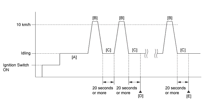


    A250733E11

    1. Warm up the engine (engine coolant temperature is 80°C (176°F) or higher, air conditioning and all accessories are off) [A].
    2. Drive the vehicle at 10 km/h (6 mph) or more [B].
    3. Idle the engine for 20 seconds or more [C].
    4. Repeat procedure [B] and [C], and check that the idle speed is within the specified range [D].

      Standard:
      Engine Idle Speed
      650 to 750 rpm

      HINT:
      1. Be sure to perform this step with all accessories off.
      2. Make sure that the shift lever is in P or N.
      3. If the idle speed is still out of the specified range, repeat procedure [B] and [C] until the idle speed is within the specified range [E].
  4. *4: Drive the vehicle for a short while after replacing the knock control sensor, and check if knocking occurs. If knocking occurs, drive the vehicle until knocking stops.

DESCRIPTION

HINT:
This registration section consists of two parts: Read VIN and Write VIN.

  1. Read VIN: Explains the VIN reading process in a flowchart. This process allows the VIN stored in the ECM to be read in order to confirm that the two VINs, provided with the vehicle and stored in the vehicle's ECM, are the same.

  2. Write VIN: Explains the VIN writing process in a flowchart. This process allows the VIN to be input into the ECM. If the ECM is changed, or the ECM VIN and vehicle VIN do not match, the VIN can be registered, or overwritten in the ECM by following this procedure.


READ VIN
  1. Confirm the vehicle VIN.

  2. Connect Techstream to the DLC3.

  3. Turn the ignition switch ON.

  4. Turn the Techstream on.

  5. Enter the following menus: Powertrain / Engine and ECT / Utility / VIN / VIN Read.


WRITE VIN
  1. Confirm the vehicle VIN.

  2. Connect Techstream to the DLC3.

  3. Turn the ignition switch ON.

  4. Turn the Techstream on.

  5. Enter the following menus: Powertrain / Engine and ECT / Utility / VIN / VIN Write.


Fuel Density Learning Value Reset (for 3UR-FBE)
  1. Connect the Techstream to the DLC3.

  2. Turn the ignition switch to ON.

  3. Turn the Techstream on.

  4. Enter the following menus: Powertrain / Engine and ECT / Utility / Fuel Density Learning Value Reset.

  5. Check that the following conditions are met.

    1. Ignition switch: ON

    2. Engine: stopped

    3. Battery voltage: 9 V or higher

  6. Press "Next".

    HINT:
    When "Next" is pressed, initialization is performed automatically.

  7. Press "Exit".


RESET MEMORY

NOTICE:
  1. Perform Reset Memory (AT initialization) when replacing the automatic transmission assembly, valve body assembly or any of the shift solenoid valves.
  2. Reset Memory can be performed only with the Techstream.

HINT:
The ECM memorizes the control conditions of the automatic transmission assembly and engine assembly. Therefore, when the automatic transmission assembly, valve body assembly or any of the shift solenoid valves has been replaced, it is necessary to reset the memory so that the ECM can memorize the new information.
The reset procedure is as follows.

  1. Connect the Techstream to the DLC3.

  2. Turn the ignition switch to ON.

  3. Turn the Techstream on.

  4. Enter the following menus: Powertrain / Engine and ECT / Utility / Reset Memory.

    NOTICE:
    After performing Reset Memory, be sure to perform the Road Test described earlier.

    HINT:
    The ECM learns through the Road Test.


DESCRIPTION OF CODE REGISTRATION
t is necessary to register the transmitter ID in the tire pressure warning ECU when replacing the tire pressure warning valve and transmitter and/or tire pressure warning ECU.
Prepare all transmitter ID data before starting registration.
  1. Before registration

    1. In case of tire pressure warning ECU replacement:

      1. Read the registered transmitter IDs that are stored in the old ECU using the Techstream and note them down.
      2. If reading stored transmitter IDs is impossible due to malfunctions of components such as the tire pressure warning antenna and receiver, remove the tires from the wheels and check the IDs located on the tire pressure warning valves and transmitters.

    2. In case of tire pressure warning valve and transmitter replacement:


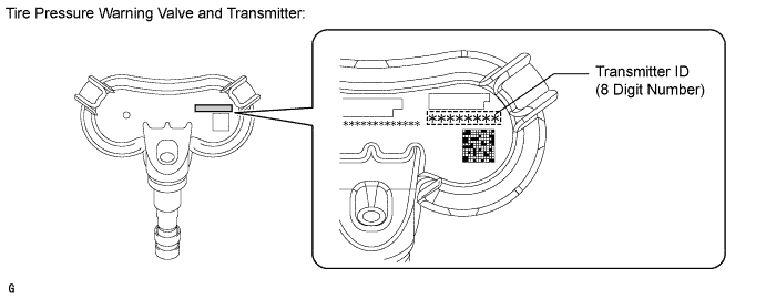
      1. Take a note of the 8 digit number (transmitter ID) written on the tire pressure warning valve and transmitter.


        C156141E01

        NOTICE:
        The transmitter ID is written on the tire pressure warning valve and transmitter. It will be unable to be read after installing the tire pressure warning valve and transmitter on the tire and wheel. Therefore, take a note of the transmitter ID before installing the tire pressure warning valve and transmitter.


REGISTER TRANSMITTER ID
  1. Set the tire pressure of all 4 tires to the specified value(s).

  2. Turn the ignition switch off.

  3. Connect the Techstream to the DLC3.

  4. Turn the ignition switch to ON and the Techstream on.

  5. Enter the following menus: Chassis / Tire Pressure Monitor / Utility / ID Registration.

  6. Perform the following procedures displayed on the screen.

  7. Confirmation of transmitter ID registration.

    1. Enter the following menus: Chassis / Tire Pressure Monitor / Data List.

    2. Read the "ID Tire Inflation Pressure" values.

    3. Confirm that the data of tire pressure of all 4 tires are displayed on the screen.

      NOTICE:
      1. It may take up to about 5 to 6 minutes to update the tire pressure data. If the values are not displayed after several minutes, perform troubleshooting according to the inspection procedure for DTCs C2121/21 to C2124/24.
      2. If the IDs have not been registered, DTC C2171/71 is set in the tire pressure warning ECU after 3 minutes or more.
      3. If normal pressure values are displayed, the IDs have been registered correctly.
      4. If the tire pressure values are not displayed after several minutes, the IDs may be incorrect or the system may have a malfunction.
      5. After all IDs are registered, DTC C2126/26 (Transmitter ID not Received in Main Mode) is set in the tire pressure warning ECU and the tire pressure warning light blinks for 1 minute and then comes on. When the tire pressure warning ECU successfully receives information from all the transmitters whose IDs are stored in the ECU, DTC C2126/26 is deleted and the tire pressure warning light goes off.


DESCRIPTION OF INITIALIZATION
  1. Perform initialization in the following cases:

    1. Before delivery of a new vehicle.
    2. After replacement of the tire pressure warning ECU*.
    3. After replacement of the tire pressure warning valve and transmitter*.

    HINT:
    *: Perform initialization after the transmitter ID registration is completed.

  2. Before initialization

    1. Set the tire pressure of all tires to the specified value(s).

      NOTICE:
      Make sure the tires are cooled down.


INITIALIZATION PROCEDURE
  1. Turn the ignition switch to ON.


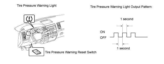
  2. Press and hold the tire pressure warning reset switch for 3 seconds or more so that the tire pressure warning light blinks 3 times.


    C158873E01

  3. Turn the ignition switch off.

  4. Connect the Techstream to the DLC3.

  5. Turn the ignition switch to ON and the Techstream on.

  6. Enter the following menus: Chassis / Tire Pressure Monitor / Data List.


  7. H102392E79
  8. Confirm that the tire pressure data of all tires are displayed on the Techstream screen in order to check the completion.

    NOTICE:
    1. The initialization is normally completed within 5 to 6 minutes.
    2. If the initialization has not been completed successfully, DTC C2177/77 is set after the vehicle is driven for 20 minutes or more.
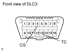
    3. The initialization can be terminated by connecting terminals 13 (TC) and 4 (CG) of the DLC3.


    Tire Pressure Monitor 
    Tester Display
    Measurement Item/Range
    Normal Condition
    Diagnostic Note
    ID 1 Tire Inflation Pressure
    ID1 tire inflation pressure /
    min.: Absolute pressure / 100.00 kPa (1 kgf/cm2, 14 psi), Relative pressure / 0 kPa (0 kgf/cm2, 0 psi)
    max.: Absolute pressure / 449.35 kPa (4.5 kgf/cm2, 63 psi), Relative pressure / 349.35 kPa (3.6 kgf/cm2, 51 psi)
    Actual tire inflation pressure
    If 100 kPa (1 kgf/cm2, 14 psi) for the absolute pressure or 0 kPa (0 kgf/cm2, 0 psi) is displayed for the relative pressure, the data has not been received.*
    ID 2 Tire Inflation Pressure
    ID2 tire inflation pressure /
    min.: Absolute pressure / 100.00 kPa (1 kgf/cm2, 14 psi), Relative pressure / 0 kPa (0 kgf/cm2, 0 psi)
    max.: Absolute pressure / 449.35 kPa (4.5 kgf/cm2, 63 psi), Relative pressure / 349.35 kPa (3.6 kgf/cm2, 51 psi)
    Actual tire inflation pressure
    If 100 kPa (1 kgf/cm2, 14 psi) for the absolute pressure or 0 kPa (0 kgf/cm2, 0 psi) is displayed for the relative pressure, the data has not been received.*
    ID 3 Tire Inflation Pressure
    ID3 tire inflation pressure /
    min.: Absolute pressure / 100.00 kPa (1 kgf/cm2, 14 psi), Relative pressure / 0 kPa (0 kgf/cm2, 0 psi)
    max.: Absolute pressure / 449.35 kPa (4.5 kgf/cm2, 63 psi), Relative pressure / 349.35 kPa (3.6 kgf/cm2, 51 psi)
    Actual tire inflation pressure
    If 100 kPa (1 kgf/cm2, 14 psi) for the absolute pressure or 0 kPa (0 kgf/cm2, 0 psi) is displayed for the relative pressure, the data has not been received.*
    ID 4 Tire Inflation Pressure
    ID4 tire inflation pressure /
    min.: Absolute pressure / 100.00 kPa (1 kgf/cm2, 14 psi), Relative pressure / 0 kPa (0 kgf/cm2, 0 psi)
    max.: Absolute pressure / 449.35 kPa (4.5 kgf/cm2, 63 psi), Relative pressure / 349.35 kPa (3.6 kgf/cm2, 51 psi)
    Actual tire inflation pressure
    If 100 kPa (1 kgf/cm2, 14 psi) for the absolute pressure or 0 kPa (0 kgf/cm2, 0 psi) is displayed for the relative pressure, the data has not been received.*

    HINT:
    1. The initialization is complete when the Data List "ID Tire Inflation Pressure" display shows the correct pressures.
    2. *: It may take up to about 5 to 6 minutes to update the tire pressure data. If the values are not displayed after about 5 to 6 minutes, perform troubleshooting according to the inspection procedure for DTCs C2121/21 to C2124/24.


CLEAR ZERO POINT CALIBRATION DATA (WHEN USING TECHSTREAM)
  1. Connect the Techstream to the DLC3.

  2. Turn the ignition switch to ON.

  3. Turn the Techstream on.

  4. Select the skid control ECU to clear the zero point calibration data using the Techstream. Enter the following menus: Chassis / ABS/VSC/TRAC / Utility / Reset Memory.


PERFORM ZERO POINT CALIBRATION OF MASTER CYLINDER PRESSURE SENSOR AND DECELERATION SENSOR (WHEN USING TECHSTREAM)

NOTICE:
  1. While obtaining the zero point, do not vibrate the vehicle by tilting, moving or shaking it and keep it stationary. (Do not start the engine.)
  2. While obtaining the zero point, do not depress the brake and accelerator pedal.
  3. Obtain the zero point on a level surface (with an inclination of 1° or less).

  1. Enter Test Mode.

    1. Turn the ignition switch off.

    2. Check that the shift lever is in parking or neutral and apply the parking brake.

      CAUTION:
      Application of the parking brake is not necessary for entering test mode. However, apply the parking brake for safety.

    3. Connect the Techstream to the DLC3.

    4. Turn the ignition switch to ON.

      NOTICE:
      Do not start the engine.

    5. Turn the Techstream on.

    6. Select the skid control ECU to Test Mode using the Techstream. Enter the following menus: Chassis / ABS/VSC/TRAC / Utility / Test Mode.

  2. Obtain the zero points of the master cylinder pressure sensor and deceleration sensor.

    1. Keep the vehicle stationary on a level surface for 1 second or more.

      HINT:
      1. The zero point calibration is performed only once after the system enters test mode.
      2. Calibration cannot be performed again until the stored data is cleared once.

    2. Check that DTC C1336 is erased.

    3. Turn the ignition switch off.


CLEAR ZERO POINT CALIBRATION DATA (WHEN USING SST CHECK WIRE)
  1. Turn the ignition switch to ON.


  2. H102392E80
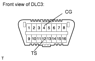
  3. Using SST, connect and disconnect terminals 12 (TS) and 4 (CG) of the DLC3 4 times or more within 8 seconds.

    SST
    09843-18040  

  4. Check that the SLIP indicator light comes on.

  5. Using a check wire, perform the zero point calibration of the deceleration sensor.


PERFORM ZERO POINT CALIBRATION OF MASTER CYLINDER PRESSURE SENSOR AND DECELERATION SENSOR (WHEN USING SST CHECK WIRE)

NOTICE:
  1. While obtaining the zero point, do not vibrate the vehicle by tilting, moving or shaking it and keep it stationary. (Do not start the engine.)
  2. While obtaining the zero point, do not depress the brake pedal.
  3. Obtain the zero point on a level surface (with an inclination of 1° or less).


  1. Enter Test Mode.

    1. Turn the ignition switch off.

    2. Check that the shift lever is in parking or neutral and apply the parking brake.

      CAUTION:
      Application of the parking brake is not necessary for entering test mode. However, apply the parking brake for safety.


    3. H102392E80
    4. Using SST, connect terminals 12 (TS) and 4 (CG) of the DLC3.

      SST
      09843-18040  

    5. Turn the ignition switch to ON.

      NOTICE:
      Do not start the engine.

  2. Obtain the zero points of the master cylinder pressure sensor and deceleration sensor.

    1. Keep the vehicle stationary on a level surface for 1 second or more.

      HINT:
      1. The zero point calibration is performed only once after the system enters test mode.
      2. Calibration cannot be performed again until the stored data is cleared once.

    2. Check that DTC C1336 is erased.

    3. Turn the ignition switch off.


PERFORM INITIALIZATION OF STEERING ANGLE SENSOR

NOTICE:
Complete the adjustment of the steering wheel and wheel alignment, and then initialize the steering angle sensor. If the order is reversed, the steering wheel and wheel alignment will become misaligned.

  1. Check that the steering wheel is in the centered position.

  2. Disconnect the negative battery terminal for more than 2 seconds.

    NOTICE:
    After the ignition switch is turned off, the navigation system requires approximately 90 seconds to record various types of memory and settings. As a result, after turning the ignition switch off, wait 90 seconds or more before disconnecting the cable from the negative (-) battery terminal.

  3. Reconnect the negative battery terminal.


ZERO POINT CALIBRATION
  1. Zero point calibration procedures:

    HINT:
    Make sure that the zero point calibration has finished normally, and then perform the sensitivity check.


    1. Check that all of the following conditions are met:

      1. The vehicle is parked on a level surface.
      2. No objects are placed on the front seat RH.
      3. The front seat inner belt RH (passenger side buckle switch) is off.

    2. Adjust the seat position in accordance with the table below.
      Adjustment Item
      Position
      Slide Direction
      Rearmost position
      Reclining Angle
      Upright position
      Headrest Height
      Lowest position
      Lifter Height
      Lowest position

    3. Connect the Techstream to the DLC3.

    4. Turn the ignition switch to ON.

    5. Perform the zero point calibration by following the prompts on the screen.

      HINT:
      1. Refer to the Techstream operator's manual for further details.
      2. If the zero point calibration has not finished normally, replace the front seat frame with adjuster assembly RH.


SENSITIVITY CHECK
  1. Sensitivity check procedures:

    1. Connect the Techstream to the DLC3.

    2. Turn the ignition switch to ON.

    3. Perform the sensitivity check by following the prompts on the screen.

      HINT:
      Refer to the Techstream operator's manual for further details.

    4. Confirm that the beginning sensor reading is within the standard range.

      Standard range:
      -3.2 to 3.2 kg (-7.0 to 7.0 lb)

    5. Place a 30 kg (66.2 lb) weight (e.g. a lead mass) onto the front passenger seat.

    6. Confirm that the sensitivity is within the standard range.

      Standard range:
      27 to 33 kg (59.5 to 72.8 lb)

      HINT:
      1. When performing the sensitivity check, use a solid metal weight (the check result may not be accurate if a liquid weight is used).
      2. If the sensitivity deviates from the standard range, retighten the bolts of the front seat RH taking care not to deform the seat rail. After performing this procedure, if the sensitivity is not within the standard range, replace the front seat frame with adjuster assembly RH.


DESCRIPTION OF CODE REGISTRATION
  1. When adding master keys or sub-keys (additional registration).

    1. Register key code in the transponder key ECU.

      Target ECU
      See Procedure
      Transponder key ECU
      Procedure "A"

  2. After replacing the transponder key ECU (New key code registration).

    1. Register the key code (immobiliser code) in the new transponder key ECU.

      Target ECU
      See Procedure
      Transponder key ECU
      Procedure "B"

    2. Register the ECU - ECM COMMUNICATION ID between the ECM and the new transponder key ECU.

      Target ECU
      See Procedure
      ECM
      Procedure "C"

  3. After replacing the ECM.

    1. Reregister the ECU - ECM COMMUNICATION ID between the new ECM and the transponder key ECU.

      Target ECU
      See Procedure
      Transponder key ECU
      Procedure "C"

  4. After replacing the transponder key ECU and ECM.

    1. Register the ECU - ECM COMMUNICATION ID between the new ECM and the new transponder key ECU.

      Target ECU
      See Procedure
      Transponder key ECU
      Procedure "C"

  5. Erasure of key codes.

    1. Erase all of the key codes except master key.

      Target ECU
      See Procedure
      Transponder key ECU
      Procedure "D"

    2. Erase all of the key codes.

      Target ECU
      See Procedure
      Transponder key ECU
      Procedure "D"


NEW KEY REGISTRATION (PROCEDURE "B")
  1. New key code registration

    HINT:
    1. This mode operates normally when no key codes are registered in the transponder key ECU.
    1. When a new transponder key ECU is installed, key codes must be registered in the transponder key ECU.
    1. In this mode, a maximum of 3 key codes for 2 master keys and 1 sub-key can be registered. The master keys and sub-key can be registered in any order because the transponder key ECU can distinguish between different types of keys.
    1. New key codes must be registered with the battery connected. The ignition switch can be either ON or OFF.

    Procedure
    Security Indicator Light Condition
    1. Start registration.
    Security indicator light is blinking.
    2. Insert one of master keys into the ignition key cylinder.
    Security indicator light turned on.
    3. Select following items on the Techstream:
    (1) Body Electrical
    (2) Immobiliser
    (3) Utility
    (4) Key Registration

    HINT:
    After above operation, proceed to next step in accordance with prompts on the screen.

    Security indicator light turned off for 1 sec. and then turned on.
    4. Remove the key.
    Security indicator light turned on.

    HINT:
    When the maximum number of the key codes is registered, the security indicator light remains off until the last key registered is removed. After it is removed, the security indicator light starts blinking.

    5. Register another key?
    YES: Go to step 6.
    NO: Go to step 7.

    HINT:
    Key codes for a maximum of 2 master keys and 1 sub-key can be registered.

    6. Insert another key into the ignition key cylinder. Then go to step 4.
    Security indicator light turned off for 1 sec. and then turned on.
    7. End of registration.

  2. End the new key code registration mode (when not using Techstream)

    HINT:
    The automatic key code registration mode can be forced to end when at least 1 key code (immobiliser code) for a master key has been registered.


    1. Turn the ignition switch ON and LOCK 5 times within 10 seconds using a master key that has already been registered.


  3. End the new key code registration mode (when using Techstream)

    HINT:
    The automatic key code registration mode can be forced to end when at least 1 key code (immobiliser code) for a master key has been registered.


    1. Insert the key into the ignition key cylinder and turn the Techstream ON.


    2. Follow the instructions on the Techstream screen to end the new key code registration mode.


      B111593E17

      HINT:
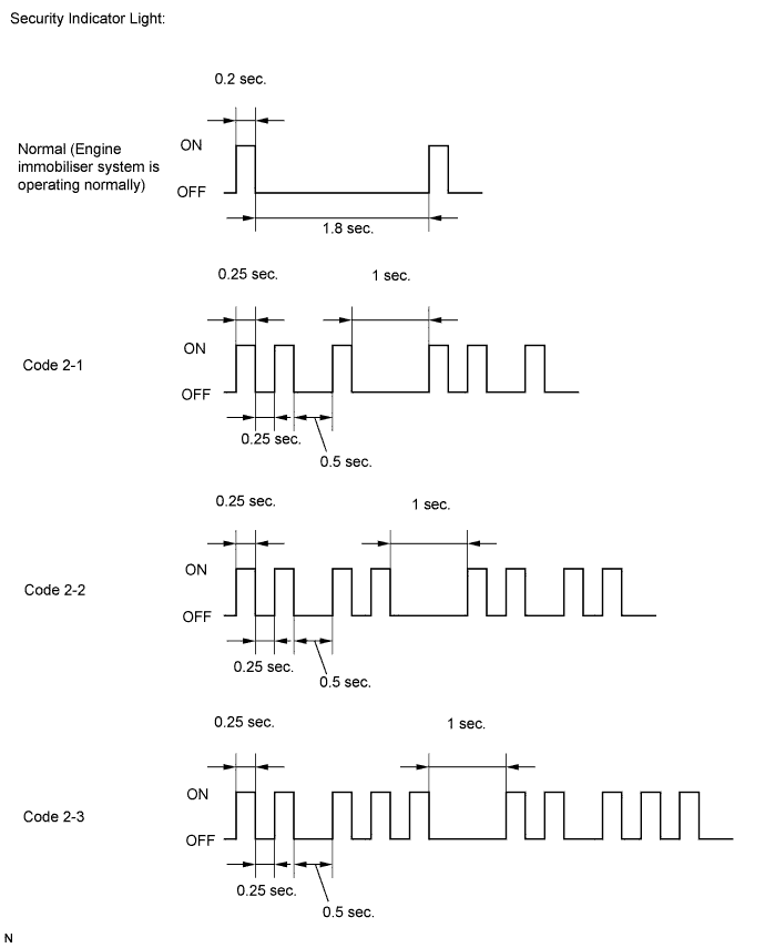
      1. When the engine immobiliser system is operating normally and the key is pulled out, the security indicator light blinks continuously.
      2. If the new key code registration fails, code 2-1 is output by the security indicator light. Trying to reregister an already registered key causes code 2-2 to be output when the key is inserted. If the number of registered key codes exceeds the limit, code 2-3 is output by the security indicator light.


REGISTRATION OF ADDITIONAL KEY (PROCEDURE "A")
  1. Additional key code registration

    HINT:
    1. At least one key code must be registered in the transponder key ECU in order for this mode to operate normally.
    2. In this mode, a maximum of 5 master key codes and 3 sub-key codes can be registered.
    3. This mode ends if each step is not completed within the specified time.
    4. When the ignition key cylinder or the ignition key cylinder set is replaced, remove the transmitter module from the original master key. Then install this transmitter module to a new key and use the new key as the master key. If necessary, use this master key to register other keys.

    NOTICE:
    When only the ignition key cylinder has been replaced, the new key cannot be used to lock or unlock doors. Therefore, keep the original key for locking and unlocking doors in order to avoid being locked out of the vehicle if the transmitter battery becomes depleted.


    Procedure
    Security Indicator Light Condition
    Time (Completion of operation)
    1. Start registration.
    Security indicator light is blinking.
    -
    2. Insert an already registered master key into the ignition key cylinder, turn the ignition switch ON, and turn the Techstream ON.
    Security indicator light turned off.
    Within 120 sec.
    3. Select following items on the Techstream:
    (1) Body Electrical
    (2) Immobiliser
    (3) Utility
    (4) Key Registration
    Security indicator light turned on.
    4. Remove the master key and then push Next button on Techstream.
    Security indicator light turned on.
    Within 20 sec. of the instruction on the Techstream.
    5. Insert unregistered key into the ignition key cylinder.
    Security indicator light is blinking.

    HINT:
    Registration is being performed.

    Within 10 sec.
    6. After 60 sec., key is registered.

    HINT:
    The security indicator light turns off.

    Security indicator light turned off.
    -
    7. Remove the key.
    Security indicator light is blinking.
    8. The screen displays number of registered keys.
    9. Register another key?
    YES: Go to step 2.
    NO: Go to step 10.
    10. End of registration.

    HINT:
    1. A brief outline of the procedures for key code registration is shown above. For more detailed information, refer to the screen of the Techstream.
    2. When the engine immobiliser system is operating normally and the key is pulled out, the security indicator light blinks continuously.
    3. If the additional key code registration fails, code 2-1 is output by the security indicator light. Trying to reregister a previously registered key causes code 2-2 to be output when the key is inserted. If the number of registered key codes exceeds the limit, code 2-3 is output by the security indicator light. The output details are shown in procedure "B".


ERASURE OF KEY CODE (PROCEDURE "D")
  1. Erasure all key codes except master key

    HINT:
    1. All key codes are erased except for the master key which is used for erasing the key codes. In order to use a key whose code has been erased, a new key code must be registered.
    2. At least one key code must be registered in the transponder key ECU in order for this mode to operate normally.
    1. Make sure the inserted key is a registered master key.

    Procedure
    Security Indicator Light Condition
    Time (Completion of operation)
    1. Start of erasure.
    Security indicator light is blinking.
    -
    2. Insert previously registered master key into ignition key cylinder and turn ignition switch ON.
    Security indicator light turned off.
    Within 120 sec.
    3. Select following items on the Techstream:
    (1) Body Electrical
    (2) Immobiliser
    (3) Utility
    (4) Transponder Code Erasure
    Security indicator light turned on for 1 sec. then turned off.
    4. Remove the master key.

    HINT:
    Key codes are deleted except inserted key.

    Security indicator light turned on.
    Within 10 sec. of the instruction on the Techstream.
    5. End of erasure.

  2. Erasure all of key codes

    HINT:
    1. This mode performs normally, when at least one key codes must be registered in the transponder key ECU.
    1. Insertion key is either registered key or unregistered key.

    Procedure
    Security Indicator Light Condition
    Time (Completion of operation)
    1. Using TIS, confirm that user and vehicle match.
    Security indicator light is blinking.
    -
    2. Start of erasure.
    Security indicator light is blinking.
    -
    3. Insert previously registered master key or unregistered key into ignition key cylinder and turn ignition switch ON.
    Security indicator light turned off.
    Within 120 sec.
    4. Select following items on the Techstream:
    (1) Body Electrical
    (2) Immobiliser
    (3) Utility
    (4) Immobiliser Code Reset
    Security indicator light turned on for 1 sec. then turned off.
    Within 15 min.
    5. Completion of erasure of all key codes is displayed.
    Security indicator light turned on.
    -
    6. End of erasure.

    HINT:
    1. A brief outline of the procedures for key code registration is shown above. For more detailed information, refer to the screen of the Techstream.
    2. When the engine immobiliser system is operating normally and the key is pulled out, the security indicator light blinks continuously.


ECU - ECM COMMUNICATION ID REGISTRATION (PROCEDURE "C")
  1. Erasure all key codes except master key

    HINT:
    1. All key codes are erased except for the master key which is used for erasing the key codes. In order to use a key whose code has been erased, a new key code must be registered.
    2. At least one key code must be registered in the transponder key ECU in order for this mode to operate normally.
    1. Make sure the inserted key is a registered master key.

    Procedure
    Security Indicator Light Condition
    Time (Completion of operation)
    1. Start of erasure.
    Security indicator light is blinking.
    -
    2. Insert previously registered master key into ignition key cylinder and turn ignition switch ON.
    Security indicator light turned off.
    Within 120 sec.
    3. Select following items on the Techstream:
    (1) Body Electrical
    (2) Immobiliser
    (3) Utility
    (4) Transponder Code Erasure
    Security indicator light turned on for 1 sec. then turned off.
    4. Remove the master key.

    HINT:
    Key codes are deleted except inserted key.

    Security indicator light turned on.
    Within 10 sec. of the instruction on the Techstream.
    5. End of erasure.

  2. Erasure all of key codes

    HINT:
    1. This mode performs normally, when at least one key codes must be registered in the transponder key ECU.
    1. Insertion key is either registered key or unregistered key.

    Procedure
    Security Indicator Light Condition
    Time (Completion of operation)
    1. Using TIS, confirm that user and vehicle match.
    Security indicator light is blinking.
    -
    2. Start of erasure.
    Security indicator light is blinking.
    -
    3. Insert previously registered master key or unregistered key into ignition key cylinder and turn ignition switch ON.
    Security indicator light turned off.
    Within 120 sec.
    4. Select following items on the Techstream:
    (1) Body Electrical
    (2) Immobiliser
    (3) Utility
    (4) Immobiliser Code Reset
    Security indicator light turned on for 1 sec. then turned off.
    Within 15 min.
    5. Completion of erasure of all key codes is displayed.
    Security indicator light turned on.
    -
    6. End of erasure.

    HINT:
    1. A brief outline of the procedures for key code registration is shown above. For more detailed information, refer to the screen of the Techstream.
    2. When the engine immobiliser system is operating normally and the key is pulled out, the security indicator light blinks continuously.


DESCRIPTION OF CODE REGISTRATION

HINT:
  1. Recognition code registration is necessary when replacing the door control transmitter or the door control receiver.
  2. Add mode is used to register new recognition codes while still retaining codes already registered. This mode is used when a new transmitter is added. If the number of registered codes exceeds 4, the previously registered codes will be erased in order, starting from the first registered code.
  3. Rewrite mode is used to erase all the previously registered recognition codes in order to register new recognition codes. This mode is used when the transmitter or the door control receiver is replaced with a new one.
  4. Confirmation mode is used to confirm how many recognition codes have already been registered before registering any additional recognition codes.
  5. Prohibition mode is used to erase all the registered codes and disables the wireless door lock function. This mode is used when the transmitter is lost.
  6. All of the following registration procedures must be performed in order and in a continuous sequence.


REGISTER RECOGNITION CODE (USING TECHSTREAM)

HINT:
For detailed procedures, refer to the prompts on the tester screen. The number of currently registered codes can be checked on the first screen of the Wireless Registration.

  1. Turn the ignition switch ON.

  2. Enter the following menus: Body Electrical / Main Body / Wireless Registration.

  3. Press both the LOCK and UNLOCK switches at the same time for 1 to 1.5 seconds.

  4. Press either switch for more than 1 second within 3 seconds.


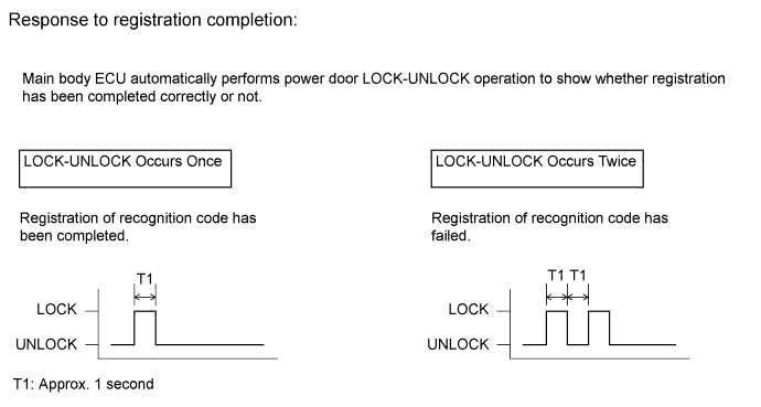
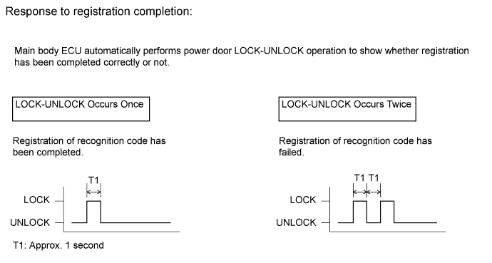
  5. Check the response to the registration completion.


    B111915E10

    HINT:
    1. If the LOCK-UNLOCK operation occurs twice, the registration of the recognition code has failed. Perform the registration procedures again from the beginning.
    2. If registering another transmitter, repeat the procedures after the tester operation. All 4 recognition codes can be registered consecutively.

  6. Perform either of the following to complete the registration of the recognition codes:

    1. Use the Techstream to send a completion command.
    2. Disconnect the Techstream.


REGISTER RECOGNITION CODE (USING SWITCH OPERATION)
  1. The following conditions must be met.

    1. No key in the ignition key cylinder.
    2. The driver side door is open (the other doors are closed).
    3. The driver side door is unlocked.

  2. Insert and remove the key into / from the ignition key cylinder twice (Insert → Remove → Insert → Remove) within 5 seconds.

    HINT:
    The procedure should end with the key removed.

  3. Perform the following operations within 40 seconds.

    1. Close and open the driver side door twice (Close → Open → Close → Open).

      HINT:
      The procedure should end with the door open.

    2. Insert and remove the key into / from the ignition key cylinder (Insert → Remove).

      HINT:
      The procedure should end with the key removed.

    3. Close and open the driver side door twice (Close → Open → Close → Open).

      HINT:
      The procedure should end with the door open.

    4. Insert the key into the ignition key cylinder and close all doors.


  4. Perform the following operations within 40 seconds.


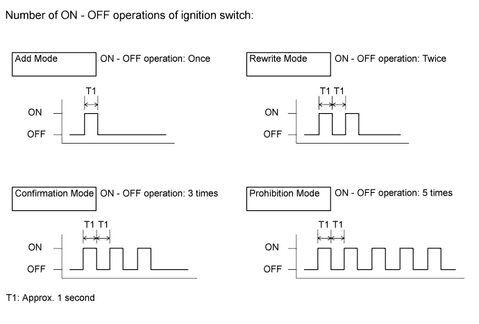
    1. Turn the ignition switch from ON to OFF at approximately 1 second intervals. Operate the ignition switch according to the number of times shown below.


      B111914E09

      HINT:
      If the number of ignition switch ON - OFF operations is 0, 4, 6 or more, there will be no response (the power door lock and unlock operation) to show which mode has been selected.

    2. Remove the key from the ignition key cylinder.


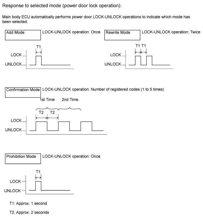
  5. Check the response of the selected mode within 5 seconds.


    B167711E02

    NOTICE:
    After the system has been set to the prohibition mode, enter the confirmation mode and check that the number of registered keys is 0.

    HINT:
    1. In the confirmation mode, LOCK-UNLOCK operation will occur once for each recognition code that has been registered. For example, if 2 recognition codes have been registered, LOCK-UNLOCK operation will occur twice.
    2. In the confirmation mode, if no recognition codes have been registered, LOCK-UNLOCK operation will occur 5 times.
    3. If confirmation mode or prohibition mode is selected, the operation ends after the response to the selected mode completes.


  6. If add mode or rewrite mode is selected, perform the following procedures.

    1. Press a single switch (LOCK or UNLOCK) within 5 seconds.


    2. After completing the above step, check the response to the registration completion within 3 seconds.


      B111915E11

      HINT:
      1. If the LOCK-UNLOCK operation occurs twice, the registration of the recognition code has failed. Perform registration procedures again from the beginning.
      2. If registering another transmitter, repeat the procedures after the response to the selected mode confirmation. All 4 recognition codes can be registered consecutively.

  7. Perform either of the following to complete the registration of the recognition codes:

    1. Open the door.
    2. Insert the key into the ignition key cylinder.


INITIALIZE POWER WINDOW CONTROL SYSTEM (POWER WINDOW REGULATOR MOTOR [for DRIVER AND FRONT PASSENGER SIDE DOORS])

NOTICE:
When the power window regulator motor is reinstalled or replaced, the power window control system must be initialized. Functions such as the AUTO UP/DOWN, jam protection and key-off do not operate if the initialization is not performed.

HINT:
When the battery is replaced, it is not necessary to initialize the power window regulator motor.

NOTICE:
  1. When performing initialization, do not perform any other procedures.
  2. After a door glass or a door glass run has been replaced, the jam protection function may operate unexpectedly when the AUTO UP function is used due to detection of a door glass movement speed that differs from the speed indicated by the operation learned value. In such cases, the AUTO UP function can be resumed by repeating the following operation at least 5 times:
    (a) Open the power window by fully pushing down the power window switch.
    (b) Close the power window by fully pulling up the power window switch and holding it at the AUTO UP position.
  3. If the initialization is not completed properly, the LIN communication system may have a malfunction.

  1. Initialization procedures when replacing the power window regulator motor with a new one.

    1. Connect the battery and turn the ignition switch to ON. At this time, the LED on the power window switch blinks to indicate that it is ready for initialization.

    2. Fully open the window by fully pushing the power window switch, and hold the switch for 1 second or more after the window is fully opened.

    3. Fully close the power window by fully pulling the power window switch, and hold the switch for 1 second or more after the window is fully closed to reset the glass position. The LED on the power window switch changes from blinking to illuminated to indicate that the initialization is complete.

  2. Initialization procedures when removing/installing the power window regulator motor or when the power window does not fully open.

    1. Connect the battery and turn the ignition switch to ON.

    2. Fully close the power window by fully pulling the power window switch, and hold the switch for 6 seconds or more after the window is fully closed. If the power window does not move or stops halfway even when the switch is fully pulled, release the switch and fully pull it again.

    3. Fully open the window by pushing down the power window switch, and hold the switch down for 1 second or more after the window is fully opened.

    4. Release the power window switch. Then fully push and hold the switch 4 seconds or more.

    5. Fully close the power window by fully pulling the power window switch, and hold the switch 1 second or more after the window is fully closed to reset the glass position. This completes the initialization.


SELECT COMPASS DISPLAY MODE
  1. The compass switch allows you to select the Display or Non-display mode of the compass.


SET ZONE
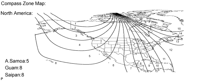
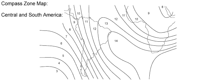
  1. Deviation between the "magnetic north" and "actual north" differs depending on the location. Therefore, adjustment of the magnetism is required. As the magnetic condition differs depending on the area where the vehicle is used, it is necessary for each user to set the zone (refer to Compass Zone Map). The zone setting can be changed using the compass switch of the inner mirror.


PERFORM CALIBRATION
  1. As each vehicle has its own magnetic field, calibration should be performed for each individual vehicle. This compass function is used when storing the record of the vehicle's magnetic field.


WHEN COMPASS IS MAGNETIZED
  1. A compass could be magnetized during shipping by vessels or freight cars. Therefore, make sure to perform calibration and ensure that calibration is performed properly before delivery. If this cannot be done (cannot be completed in spite of driving around several times), it may be caused by magnetization. Demagnetize the vehicle using a demagnetizer and perform calibration again.


SET COMPASS

B167457E01


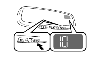
ZONE SETTING MODE


    B231509
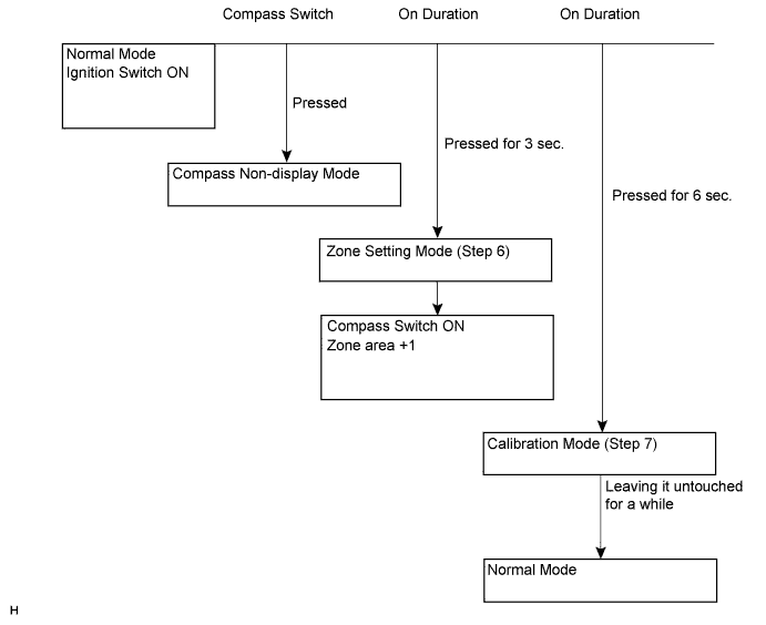
  1. Pressing the compass switch for 3 seconds in the normal mode will activate the zone setting mode. A number (1 - 15) is displayed on the compass display.

    HINT:
    In the initial state, "10" is displayed.

  2. The displayed number increases +1 every time the compass switch is pressed. Referring to the map, check the number for the area where the vehicle will be used and set the zone number.

  3. Leave it untouched for several seconds after setting and check that the compass display shows an azimuthal direction (N, NE, E, SE, S, SW, W or NW) or "CAL".


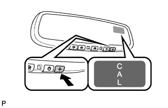
CALIBRATION SETTING MODE


    B231513
  1. Pressing the compass switch for 6 seconds in the normal mode will activate the calibration setting mode. "CAL" is displayed on the compass display.

  2. Drive the vehicle at a slow speed of 8 km/h (5 mph) or less in a circular direction.

  3. Driving in a circle 1 to 3 times will display the azimuthal direction on the display, completing the calibration.

    HINT:
    After the calibration is completed, it is not necessary to perform the above procedures unless the magnetic field strength is drastically changed. If this happens, the azimuthal display will be changed to "CAL".


  4. The zone setting numbers are as follows:


    B231510E03


    B231496E01


REGISTER TRANSMITTER CODE

HINT:
  1. The vehicle's garage door opener records transmitter codes for systems such as garage doors, gates, entry gates, door locks, home lighting systems, security systems or other transmitter code based systems.
  2. The garage door opener is built into the inner rear view mirror. If replacing the inner rear view mirror, transmitter codes for any systems previously registered in the garage door opener must be reregistered.


  1. Reregister systems in the garage door opener registration mode.

    CAUTION:
    Do not perform transmitter code registration for a system if people or objects are near the system. When registering transmitter codes for a system, injury or damage can occur because the system may open, close, unlock or otherwise operate.

    NOTICE:
    1. Before transmitter code registration, confirm that all the electrical systems (headlight, blower motor, rear defogger, etc.) are turned off and no key is in the vehicle.
    2. The garage door opener cannot be used with systems that: 1) were manufactured before April 1, 1982; or 2) do not meet Federal Standards (for example, garage doors without a jam protection function).

    HINT:
    1. 3 transmitter codes can be registered with the garage door opener, one transmitter code for each of the 3 garage door opener switches.
    2. Disconnecting the battery will not erase the transmitter codes registered with the garage door opener.
    3. An attempt to overwrite a previously registered transmitter code with a new system's transmitter code may fail. In this situation, the previously registered transmitter code will not be erased.


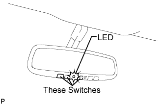
    1. Select a garage door opener switch for transmitter code registration.


    2. B165760E01
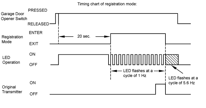
    3. Press and hold the selected switch for 20 seconds. The garage door opener will enter registration mode.

      HINT:
      Before entering registration mode, the LED illuminates. After entering registration mode, the LED flashes at a cycle of 1 Hz. For a "rolling code" type system, after entering registration mode, the LED flashes at a cycle of 8.8 Hz for 1.6 seconds, and then the LED flashes at a cycle of 1 Hz.


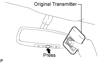
    4. B166263E01
    5. After the garage door opener has entered registration mode, bring the original transmitter of the system to be registered within 1 to 3 inches of the garage door opener and press and hold one of the garage door opener switches. Then press the original transmitter switch.


    6. If the transmitter code registration was successful, the LED of the garage door opener flashes at a cycle of 5.6 Hz. If no malfunction occurs, release both the garage door opener switch and the original transmitter switch.

      HINT:
      1. If transmitter code registration fails: 1) the original transmitter's battery may be low or need to be replaced, or 2) the system you are trying to register may not be compatible with the garage door opener.
      2. Some transmitter's signals stop after 1 to 2 seconds. For these types of transmitters: 1) press and hold one of the garage door opener switches, and 2) press and release (cycle) the transmitter switch every 2 seconds. Check if the transmitter code was successfully registered.
      3. After entering the garage door opener registration mode, transmitter code registration must be completed within 90 seconds. If 90 seconds elapse, the garage door opener will enter low power mode (refer to "low power mode" below).


      I003487E18


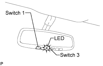
  2. B165760E02
  3. Erase transmitter codes in the garage door opener clear mode.

    HINT:
    All 3 registered transmitter codes will be erased. No option exists for only erasing one transmitter code.


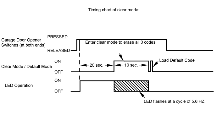
    1. Press and hold the left and right switches of the garage door opener for 20 seconds. The LED will begin to flash at a cycle of 5.6 Hz. Releasing the switches will end clear mode.

      HINT:
      1. If the switches are released within 10 seconds after the transmitter codes have been erased, the garage door opener will enter registration mode.
      2. If the switches are held for 10 seconds or more after the transmitter codes have been erased, default codes will be set to the switches of the garage door opener. Using these default codes, operation of the garage door opener can be checked using a tester.


      B167790E01

  4. Low power mode:

    1. If a garage door opener switch is held for 100 seconds or more, the garage door opener will enter low power mode to economize on power consumption. When the garage door opener has entered low power mode, the LED turns off.


INITIALIZE SLIDING ROOF DRIVE GEAR SUB-ASSEMBLY

NOTICE:
When replacing the sliding roof drive gear, the new sliding roof drive gear requires initialization. If a reset is not executed, the following functions do not operate: AUTO operation and jam protection function.

  1. Turn the ignition switch ON.

  2. By pushing the SLIDE switch to close or the TILT switch to up on the roof console box, make the sliding roof operate as follows:
    TILT UP → approximately 1 second → TILT UP (The sliding roof lowers a little after it is fully tilted up.)

  3. Check that the sliding roof stops at the fully closed position.

  4. Finish the initialization.

  5. Check that the AUTO operation works normally.

    NOTICE:
    If the following conditions occur while operating, initialization will fail.
    1. Ignition switch is turned off.
    2. Pushed sliding roof switch is released while sliding roof is operating.

    HINT:
    1. If the sliding roof cannot fully close or its position has become misaligned, perform the initialization again.
    2. If the sliding roof TILT switch to up or SLIDE switch to close is pressed and held until the roof glass has either stopped moving or started moving in the opposite direction, and then the switch is held for another 10 seconds or more, perform the initialization again.
    3. If the AUTO operation function and jam protection function do not operate after the drive gear has been initialized, replace the sliding roof drive gear (sliding roof ECU).