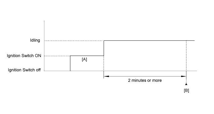
DTC P1613 Secondary Air Injection Driver Malfunction |
DTC P1614 Secondary Air Injection System Driver Bank 2 |
| DTC No. | DTC Detection Condition | Trouble Area |
| P1613 P1614 | Either of following conditions (1) or (2) met: (1) All of following conditions met (1 trip detection logic):
|
|
| P1613 P1614 |
|
|
| P1613 P1614 |
|
|
| Related DTCs | P1613: Secondary air injection system air injection control driver circuit range check P1614: Secondary air injection system air injection control driver circuit range check |
| Required Sensors/Components (Main) | Air injection control driver |
| Required Sensors/Components (Related) | Air switching valve |
| Frequency of Operation | Once per drive cycle |
| Duration | 3 seconds |
| MIL Operation | Immediate |
| Sequence of Operation | None |
| Monitor runs whenever following DTCs not stored | None |
| Battery voltage | 8 V or more |
| Ignition switch | ON |
| Starter | OFF |
| Monitor runs whenever following DTCs not stored | None |
| Either a or b met: | - |
| a. Air pump | Not operating |
| b. Air switching valve | Not operating |
| Battery voltage | 8 V or more |
| Ignition switch | ON |
| Starter | OFF |
| Monitor runs whenever following DTCs not stored | None |
| Following conditions (a) and (b) met | - |
| a. Air pump | Operating |
| b. Air switching valve | Operating |
| Battery voltage | 8 V or more |
| Ignition switch | ON |
| Starter | OFF |
| One of following conditions met: | A, B, C or D |
| A. Diagnostic signal duty ratio from air injection control driver | 1% or more, and 10% or less |
| B. Diagnostic signal duty ratio from air injection control driver | 30% |
| C. Diagnostic signal duty ratio from air injection control driver | 49% |
| D. Diagnostic signal duty ratio from air injection control driver | 91% or more, and 99% or less |
| Diagnostic signal duty ratio from air injection control driver | 70% or more, and 90% or less |
| Diagnostic signal duty ratio from air injection control driver | 0% |
| Diagnostic signal duty ratio from air injection control driver | 100% |
| Diagnostic signal duty ratio from air injection control driver | 70% or more, and 90% or less when secondary air injection system operating. 0% when secondary air injection system not operating. |
| Tester Display | Description |
| NORMAL |
|
| ABNORMAL |
|
| INCOMPLETE |
|
| N/A |
|
| 1.CHECK ANY OTHER DTCS OUTPUT (IN ADDITION TO DTC P1613 OR P1614) |
Connect the Techstream to the DLC3.
Turn the ignition switch to ON and turn the Techstream on.
Enter the following menus: Powertrain / Engine and ECT / Trouble Codes.
Read DTCs.
| Result | Proceed to |
| P1613 and/or P1614 are output | A |
| P1613 and/or P1614 and other DTCs are output | B |
|
| ||||
| A | |
 |
| 2.CHECK AIR INJECTION CONTROL DRIVER (POWER SOURCE CIRCUIT) |
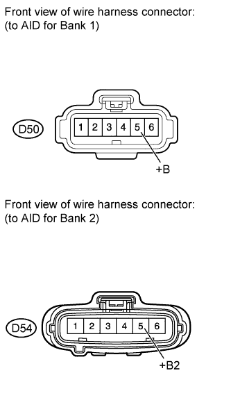 |
Disconnect the D50 or D54 AID connector.
Turn the ignition switch to ON.
Measure the voltage according to the value(s) in the table below.
| Tester Connection | Switch Condition | Specified Condition |
| D50-5 (+B) - Body ground | Ignition switch ON | 11 to 14 V (near battery voltage) |
| D54-5 (+B2) - Body ground | Ignition switch ON | 11 to 14 V (near battery voltage) |
|
| ||||
| OK | |
|
| 3.CHECK HARNESS AND CONNECTOR (AID - ECM, BODY GROUND) |
Disconnect the A24 or D74 ECM connector.
Disconnect the D50 or D54 AID connector.
Measure the resistance according to the value(s) in the table below.
| Tester Connection | Condition | Specified Condition |
| D74-54 (AIRP) - D50-4 (SIP) | Always | Below 1 Ω |
| D74-28 (AIRV) - D50-3 (SIV) | Always | Below 1 Ω |
| D74-53 (ARP2) - D54-4 (SIP2) | Always | Below 1 Ω |
| A24-43 (ARV2) - D54-3 (SIV2) | Always | Below 1 Ω |
| D74-30 (AIDI) - D50-2 (DI) | Always | Below 1 Ω |
| D74-29 (AID2) - D54-2 (DI2) | Always | Below 1 Ω |
| D50-1 (E) - Body ground | Always | Below 1 Ω |
| D54-1 (E2) - Body ground | Always | Below 1 Ω |
| D74-54 (AIRP) or D50-4 (SIP) - Body ground | Always | 10 kΩ or higher |
| D74-28 (AIRV) or D50-3 (SIV) - Body ground | Always | 10 kΩ or higher |
| D74-53 (ARP2) or D54-4 (SIP2) - Body ground | Always | 10 kΩ or higher |
| A24-43 (ARV2) or D54-3 (SIV2) - Body ground | Always | 10 kΩ or higher |
| D74-30 (AIDI) or D50-2 (DI) - Body ground | Always | 10 kΩ or higher |
| D74-29 (AID2) or D54-2 (DI2) - Body ground | Always | 10 kΩ or higher |
|
| ||||
| OK | |
|
| 4.INSPECT AIR INJECTION CONTROL DRIVER (DI TERMINAL VOLTAGE) |
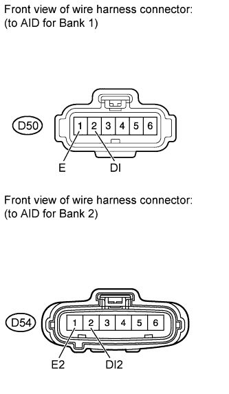 |
Disconnect the D50 or D54 AID connector.
Turn the ignition switch to ON.
Measure the voltage according to the value(s) in the table below.
| Tester Connection | Switch Condition | Specified Condition |
| D50-2 (DI) - D50-1 (E) | Ignition switch ON | 11 to 14 V (near battery voltage) |
| D54-2 (DI2) - D54-1 (E2) | Ignition switch ON | 11 to 14 V (near battery voltage) |
|
| ||||
| OK | |
|
| 5.PERFORM ACTIVE TEST USING TECHSTREAM |
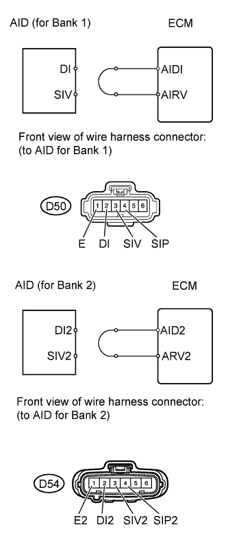 |
Disconnect the D50 or D54 AID connector.
Connect terminals DI and SIV or DI2 and SIV2 of the wire harness connector for the AID.
Connect the Techstream to the DLC3.
Turn the ignition switch to ON and turn the Techstream on.
Enter the following menus: Powertrain / Engine and ECT / Utility / Secondary Air Injection Check / Manual Mode / AIR PUMP 1: ON, ASV 1: OPEN, AIR PUMP 2: ON, ASV 2: OPEN.
Start the engine.
Perform the AIR system forced operation while the engine is idling.
Measure the voltage between the SIV and E or SIV2 and E2 terminals of the ECM connector when the AIR system is ON and OFF.
Turn the ignition switch off.
| Tester Connection | Condition | Specified Condition |
| D50-3 (SIV) - D50-1 (E) | AIR PUMP: ON, ASV: OPEN | 0.5 to 2 V |
| D54-3 (SIV2) - D54-1 (E2) | AIR PUMP: ON, ASV: OPEN | 0.5 to 2 V |
| D50-3 (SIV) - D50-1 (E) | AIR PUMP: OFF, ASV: CLOSE | 11 to 14 V |
| D54-3 (SIV2) - D54-1 (E2) | AIR PUMP: OFF, ASV: CLOSE | 11 to 14 V |
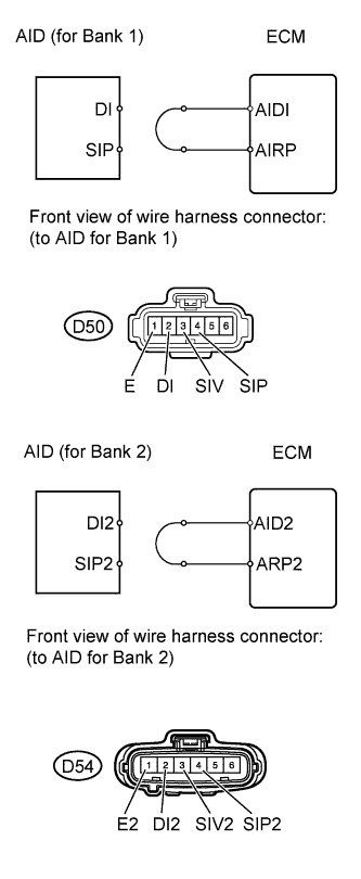 |
Connect terminals DI and SIP or DI2 and SIP2 of the wire harness connector for the AID.
Connect the Techstream to the DLC3.
Turn the ignition switch to ON and turn the Techstream on.
Enter the following menus: Powertrain / Engine and ECT / Utility / Secondary Air Injection Check / Manual Mode / AIR PUMP 1: ON, ASV 1: OPEN, AIR PUMP 2: ON, ASV 2: OPEN.
Start the engine.
Perform the AIR system forced operation while the engine is idling.
Measure the voltage between the SIP and E or SIP2 and E2 terminals of the ECM connector when the AIR system is ON and OFF.
Turn the ignition switch off.
| Tester Connection | Condition | Specified Condition |
| D50-4 (SIP) - D50-1 (E) | AIR PUMP: ON, ASV: OPEN | 0.5 to 2 V |
| D54-4 (SIP2) - D54-1 (E2) | AIR PUMP: ON, ASV: OPEN | 0.5 to 2 V |
| D50-4 (SIP) - D50-1 (E) | AIR PUMP: OFF, ASV: CLOSE | 11 to 14 V |
| D54-4 (SIP2) - D54-1 (E2) | AIR PUMP: OFF, ASV: CLOSE | 11 to 14 V |
|
| ||||
| OK | |
|
| 6.REPLACE AIR INJECTION CONTROL DRIVER |
Replace the air injection control driver (Click here).
| NEXT | |
|
| 7.CONFIRM WHETHER DTC OUTPUT RECURS |
Start the engine and warm it up.
Turn the ignition switch off.
Connect the Techstream to the DLC3.
Turn the ignition switch to ON and turn the Techstream on.
Clear DTCs (Click here).
Enter the following menus: Powertrain / Engine and ECT / Utility / Secondary Air Injection Check / Automatic Mode.
Start the engine after the Techstream initialization is finished.
Perform the System Check operation by pressing Next.
After operating the AIR system, perform the following to confirm the AIR system pending codes: Press the Exit button.
Enter the following menus: Powertrain / Engine and ECT / Trouble Codes / Pending.
Read DTCs.
| Result | Proceed to |
| No DTC is output | A |
| Other DTCs are output | B |
Turn the ignition switch off.
|
| ||||
| A | ||
 | ||
| ||
