 |
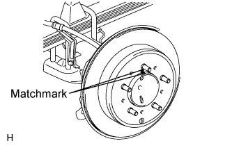
Align the matchmarks and install the rear disc.
REAR BRAKE > INSTALLATION |
| 1. INSTALL REAR DISC |
|
Align the matchmarks and install the rear disc.
| 2. ADJUST PARKING BRAKE SHOE CLEARANCE |
Temporarily install the hub nuts.
Remove the hole plug.
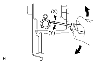 |
Insert a screwdriver into the adjustment hole of the disc. Rotate the adjustment wheel in the "X" direction until the shoes are locked. Then rotate the adjustment wheel in the "Y" direction 8 notches.
Check that the disc can be rotated smoothly. If not, rotate the adjustment wheel in the "Y" direction and check again.
Install the hole plug.
Remove the hub nuts.
| 3. INSTALL REAR DISC BRAKE CYLINDER MOUNTING LH |
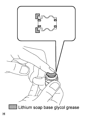 |
Apply a light coat of lithium soap base glycol grease to the entire circumference of a new rear disc brake bush dust boot where it contacts the rear disc brake mounting cylinder, and the entire inner circumference of both ends.
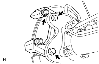 |
Install the rear disc brake bush dust boot to the rear disc brake cylinder mounting.
Install the rear disc brake cylinder mounting with the 2 bolts.
| 4. INSTALL REAR DISC BRAKE PAD SUPPORT PLATE |
Clean the cylinder mounting surface where the pad support plates will be attached.
Remove the peeling paper from the double-sided tape, and install 4 new pad support plates to the cylinder mounting.
| 5. INSTALL PAD WEAR INDICATOR PLATE |
Install the pad wear indicator plate to the inner disc brake pad.
| 6. INSTALL REAR DISC BRAKE ANTI-SQUEAL SHIM |
Install the anti-squeal shims to the each brake pads.
| 7. INSTALL REAR DISC BRAKE PAD |
Install the 2 disc brake pads to the disc brake cylinder mounting.
| 8. INSTALL REAR DISC BRAKE CYLINDER ASSEMBLY LH |
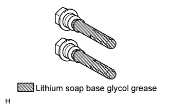 |
Apply a light coat of lithium soap base glycol grease to the sliding part and seal surface of the 2 slide pins.
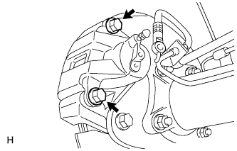 |
Install the 2 slide pins.
| 9. CONNECT REAR FLEXIBLE HOSE LH |
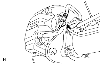 |
Install a new gasket and connect the flexible hose with the new union bolt.
| 10. BLEED BRAKE LINE |
Bleed brake line
Remove the brake master cylinder reservoir filler cap assembly.
Add brake fluid into the reservoir between MAX and MIN level on the brake fluid reservoir.
Connect a vinyl tube to the bleeder plug of the front disc brake cylinder RH.
Depress the brake pedal several times, and then loosen the bleeder plug with the pedal depressed.*1
When fluid stops coming out, tighten the bleeder plug, and then release the brake pedal.*2
Repeat *1 and *2 until all the air in the brake fluid is completely bled out and the new brake fluid comes out.
Tighten the bleeder plug completely.
Replace the brake fluid from the front disc brake cylinder LH using the same procedure as for RH.
Connect a vinyl tube to the bleeder plug of the rear disc brake cylinder RH.
Depress the brake pedal several times, and then loosen the bleeder plug with the pedal depressed.*1
When fluid stops coming out, tighten the bleeder plug, and then release the brake pedal.*2
Repeat *1 and *2 until all the air in the brake fluid is completely bled out and the new brake fluid comes out.
Tighten the bleeder plug completely.
Replace the brake fluid from the rear disc brake cylinder LH using the same procedure as for RH.
Check and bleed brake system.
If the following malfunction symptoms occur, air may have entered the brake fluid line. Perform the following air bleed procedures.
Check and adjust brake fluid level in reservoir .
| 11. INSTALL REAR WHEEL |