 |
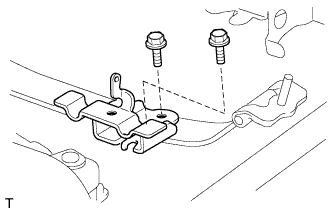
Install the bracket with the 2 bolts.
- Torque:
- 19 N*m{ 194 kgf*cm , 14 ft.*lbf }
PARKING BRAKE CABLE > INSTALLATION |
| 1. INSTALL NO. 2 CABLE SUPPORT BRACKET |
|
Install the bracket with the 2 bolts.
| 2. INSTALL PARKING BRAKE INTERMEDIATE LEVER SUB-ASSEMBLY |
Apply MP grease to the moving parts of the intermediate lever.
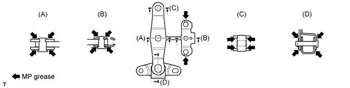
Apply MP grease to the areas where the cables contact the intermediate lever.
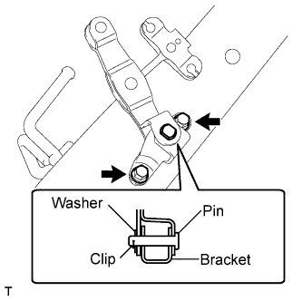 |
Install the intermediate lever to the bracket with the clip, washer and pin.
Install the intermediate lever with bracket with the 2 bolts.
| 3. INSTALL NO. 3 PARKING BRAKE CABLE ASSEMBLY |
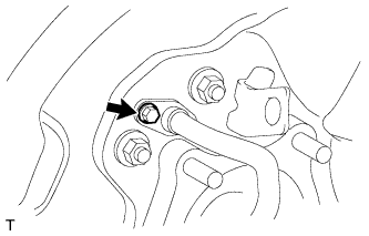 |
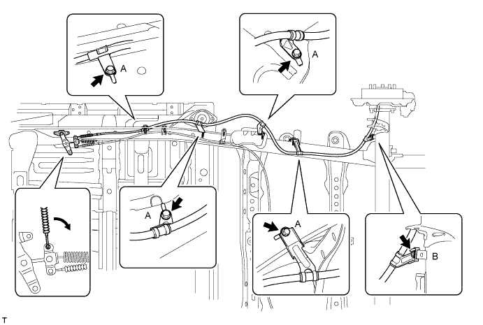
Install the No. 3 parking brake cable to the rear axle carrier with the bolt.
Connect the No. 3 parking brake cable to the intermediate lever and install the 5 bolts.
| 4. INSTALL PARKING BRAKE SHOE LEVER LH |
Apply high temperature grease to the parking brake shoe lever.
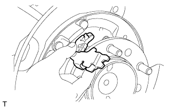 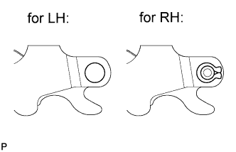 |
Install the parking brake shoe lever to the No. 3 parking brake cable.
| 5. INSTALL NO. 2 PARKING BRAKE SHOE ASSEMBLY LH |
Apply high temperature grease to the areas of the backing plate that contact the shoe.
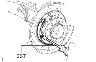 |
Using SST, install the No. 2 parking brake shoe with the shoe hold down spring pin, compression spring and shoe hold down spring cup.
| 6. INSTALL NO. 1 PARKING BRAKE SHOE ASSEMBLY LH |
Apply high temperature grease to the areas of the backing plate that contact the shoe.
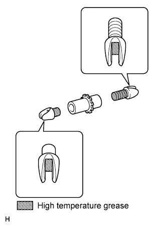 |
Apply the high temperature grease to the areas of the shoe adjusting screw set shown in the illustration.
Set the parking brake shoe and shoe adjuster screw set in place.
Connect the tension spring.
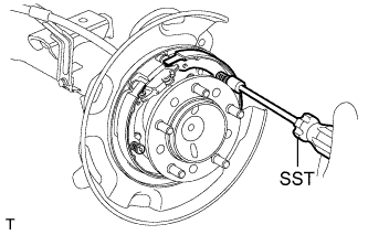 |
Using SST, install the No. 1 parking brake shoe with the shoe hold down spring pin, compression spring and shoe hold down spring cup.
| 7. INSTALL PARKING BRAKE SHOE RETURN SPRING LH |
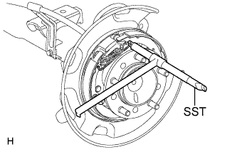 |
Using SST, install the shoe return spring.
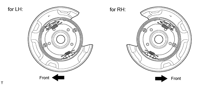
| 8. CHECK PARKING BRAKE INSTALLATION |
Check that each part is installed properly.
| 9. INSTALL REAR DISC LH |
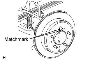 |
Align the matchmarks and install the rear disc.
| 10. ADJUST PARKING BRAKE SHOE CLEARANCE |
Temporarily install the hub nuts.
Remove the hole plug.
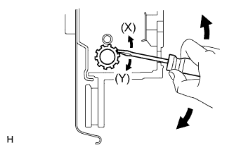 |
Insert a screwdriver into the adjustment hole of the disc. Rotate the adjustment wheel in the "X" direction until the shoes are locked. Then rotate the adjustment wheel in the "Y" direction 8 notches.
Check that the disc can be rotated smoothly. If not, rotate the adjustment wheel in the "Y" direction and check again.
Install the hole plug.
Remove the hub nuts.
| 11. CONNECT REAR DISC BRAKE CYLINDER ASSEMBLY LH |
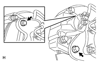 |
Connect the rear disc brake cylinder with 2 new bolts.
| 12. INSTALL REAR WHEEL LH |
| 13. INSTALL NO. 2 PARKING BRAKE CABLE ASSEMBLY |
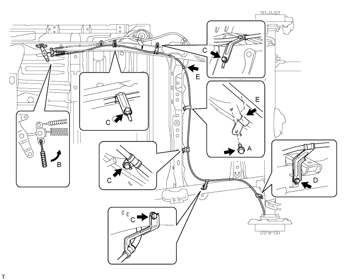
Install the clamp with the bolt (labeled A).
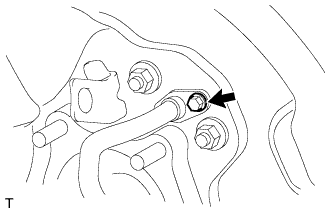 |
Install the No. 2 parking brake cable to the rear axle carrier with the bolt.
Connect the No. 2 parking brake cable to the intermediate lever (labeled B) and install the 5 bolts (labeled C and D).
Connect the No. 2 parking brake cable to the 2 clamps (labeled E).
| 14. INSTALL NO. 2 CABLE RETAINER |
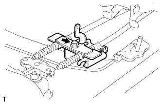 |
Install the retainer with the bolt.
| 15. INSTALL INTERMEDIATE LEVER TENSION SPRING |
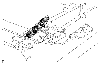 |
Install the tension spring.
| 16. INSTALL PARKING BRAKE SHOE LEVER RH |
| 17. INSTALL NO. 2 PARKING BRAKE SHOE ASSEMBLY RH |
| 18. INSTALL NO. 1 PARKING BRAKE SHOE ASSEMBLY RH |
| 19. INSTALL PARKING BRAKE SHOE RETURN SPRING RH |
| 20. CHECK PARKING BRAKE INSTALLATION |
Check that each part is installed properly.
| 21. INSTALL REAR DISC RH |
| 22. ADJUST PARKING BRAKE SHOE CLEARANCE |
Temporarily install the hub nuts.
Remove the hole plug.
|
Insert a screwdriver into the adjustment hole of the disc. Rotate the adjustment wheel in the "X" direction until the shoes are locked. Then rotate the adjustment wheel in the "Y" direction 8 notches.
Check that the disc can be rotated smoothly. If not, rotate the adjustment wheel in the "Y" direction and check again.
Install the hole plug.
Remove the hub nuts.
| 23. CONNECT REAR DISC BRAKE CYLINDER ASSEMBLY RH |
| 24. INSTALL REAR WHEEL RH |
| 25. INSTALL NO. 1 PARKING BRAKE CABLE ASSEMBLY (for 3220 mm [10 ft. 6.8 in.] Wheelbase Type) |
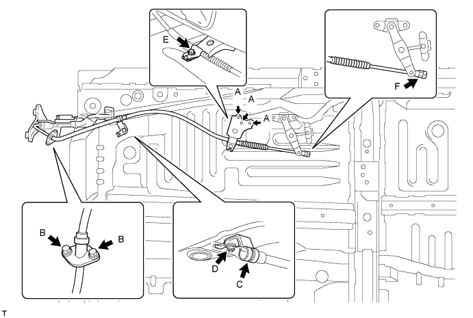
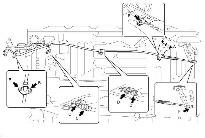
Install the No. 1 cable support bracket with the 3 bolts (labeled A).
Install the No. 1 parking brake cable to the inside of the vehicle with the 2 bolts (labeled B).
Connect the clamp (labeled C) to the No. 1 parking brake cable.
Install the clamp with the nut (labeled D).
Install the No. 1 parking brake cable and cable retainer with the bolt (labeled E).
Temporarily install the adjustment nut and lock nut (labeled F).
| 26. INSTALL NO. 1 PARKING BRAKE CABLE ASSEMBLY (for 3700 mm [12 ft. 1.7 in.] Wheelbase Type) |
Install the No. 1 cable support bracket with the 3 bolts (labeled A).
Install the No. 1 parking brake cable to the inside of the vehicle with the 2 bolts (labeled B).
Connect the 2 clamps (labeled C) to the No. 1 parking brake cable.
Install the 2 clamps with the 2 nuts (labeled D).
Install the No. 1 parking brake cable and cable retainer with the bolt (labeled E).
Temporarily install the adjustment nut and lock nut (labeled F).
| 27. INSTALL NO. 1 PARKING BRAKE CABLE ASSEMBLY (for 4180 mm [13 ft. 8.6 in.] Wheelbase Type) |
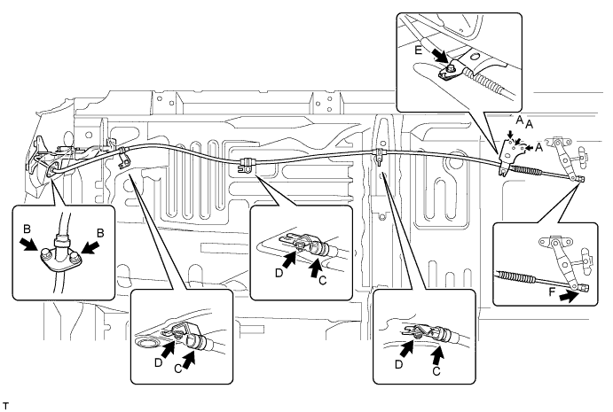
Install the No. 1 cable support bracket with the 3 bolts (labeled A).
Install the No. 1 parking brake cable to the inside of the vehicle with the 2 bolts (labeled B).
Connect the 3 clamps (labeled C) to the No. 1 parking brake cable.
Install the 3 clamps with the 3 nuts (labeled D).
Install the No. 1 parking brake cable and cable retainer with the bolt (labeled E).
Temporarily install the adjustment nut and lock nut (labeled F).
| 28. INSTALL FRONT NO. 2 EXHAUST PIPE ASSEMBLY (for 1GR-FE) |
for Regular Cab Standard Deck:
Install the front No. 2 exhaust pipe .
except Regular Cab Standard Deck:
Install the front No. 2 exhaust pipe .
| 29. INSTALL FRONT NO. 3 EXHAUST PIPE SUB-ASSEMBLY (for 1GR-FE) |
for Regular Cab Standard Deck:
Install the front No. 3 exhaust pipe .
| 30. INSTALL FRONT NO. 2 EXHAUST PIPE ASSEMBLY (for 1UR-FE) |
for Regular Cab Standard Deck:
Install the front No. 2 exhaust pipe .
except Regular Cab Standard Deck:
Install the front No. 2 exhaust pipe .
| 31. INSTALL FRONT NO. 2 EXHAUST PIPE ASSEMBLY (for 3UR-FE) |
for Regular Cab Standard Deck:
Install the front No. 2 exhaust pipe .
except Regular Cab Standard Deck:
Install the front No. 2 exhaust pipe .
| 32. INSTALL FRONT NO. 2 EXHAUST PIPE ASSEMBLY (for 3UR-FBE) |
except Regular Cab Standard Deck:
Install the front No. 2 exhaust pipe .
| 33. REMOVE FRONT NO. 3 EXHAUST PIPE SUB-ASSEMBLY (for 1UR-FE) |
for Regular Cab Standard Deck:
Install the front No. 3 exhaust pipe .
| 34. INSTALL FRONT NO. 3 EXHAUST PIPE SUB-ASSEMBLY (for 3UR-FE) |
for Regular Cab Standard Deck:
Install the front No. 3 exhaust pipe .
| 35. INSTALL NO. 3 EXHAUST PIPE SUB-ASSEMBLY (for 3UR-FBE) |
for Regular Cab Standard Deck:
Install the front No. 3 exhaust pipe .
| 36. CONNECT NO. 1 PARKING BRAKE CABLE ASSEMBLY |
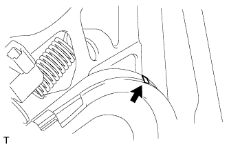 |
Connect the parking brake cable to the control pedal.
Using needle-nose pliers, slowly bend down the claw.
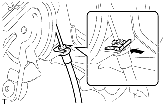 |
Install the clip to the control pedal.
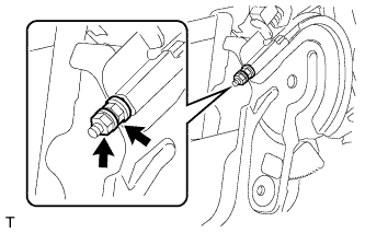 |
Temporarily install the adjustment nut and lock nut.
| 37. SETTLE PARKING BRAKE SHOE AND DISC |
Drive the vehicle for approximately 400 m (0.25 miles) under the following conditions.
The vehicle speed is approximately 50 km/h (31 mph) and the vehicle is on a safe, level and dry road.
The parking brake pedal is being depressed with a force of 150 N (15 kgf, 33.7 lbf).
Repeat the procedures above 2 or 3 times.
| 38. CHECK PARKING BRAKE PEDAL TRAVEL |
Firmly depress the parking brake pedal.
Release the parking brake.
Slowly depress the parking brake pedal with a force of approximately 300 N (31 kgf, 67.4 lbf) and count the number of clicks.
| 39. ADJUST PARKING BRAKE PEDAL TRAVEL |
Depress the parking brake pedal.
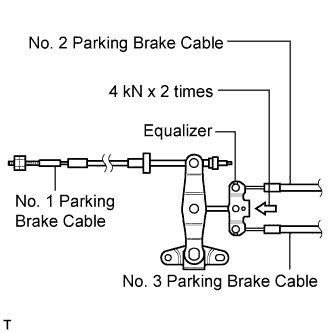 |
Apply load equivalent to 4 kN (408 kgf, 899.2 lbf) on equalizer twice to pull No. 2 and No. 3 parking brake cable to remove initial elongation.
Release the parking brake pedal to the original position.
|
Loosen the pedal side No. 1 parking brake cable lock nut.
Turn the pedal side No. 1 parking brake cable adjustment nut until the parking brake pedal travel is correct.
| Pedal Load | Specified Condition |
| 300 N (31 kgf, 67.4 lbf) | 6 to 9 clicks |
Using a wrench or equivalent to hold the adjustment nut, tighten the lock nut.
Additionally, excessive pedal travel can be adjusted on the No. 1 parking brake cable underbody side as follows.
Release the parking brake pedal to the original position.
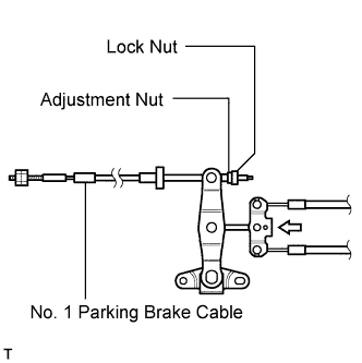 |
Loosen the underbody side No. 1 parking brake cable lock nut.
Turn the underbody side No. 1 parking brake cable adjustment nut until the parking brake pedal travel is correct.
| Pedal Load | Specified Condition |
| 300 N (31 kgf, 67.4 lbf) | 6 to 9 clicks |
Tighten the No. 1 parking brake cable underbody lock nut.
Depress and release the parking brake pedal 3 or 4 times. Then check the number of clicks when depressing the pedal.
Check whether the parking brake drags or not.
If the parking brake drags, adjust the shoe clearance.
When operating the parking brake pedal, check that the parking brake pedal indicator light comes on at the first notch.
If not, adjust the parking brake switch installation position.
| 40. INSTALL LOWER NO. 1 INSTRUMENT PANEL AIRBAG ASSEMBLY |
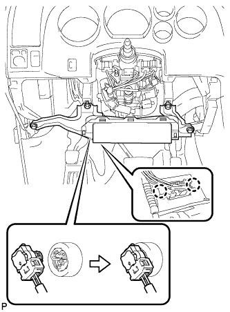 |
Connect the connector.
Attach the 2 claws to install the DLC3.
Install the 4 bolts to install the instrument panel airbag.
| 41. INSTALL LOWER INSTRUMENT PANEL FINISH PANEL SUB-ASSEMBLY LH |
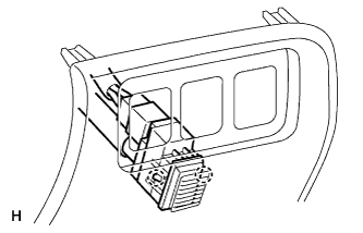 |
for Automatic Air Conditioning System:
Attach the 2 claws to install the sensor.
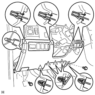 |
Connect the connectors.
Attach the 9 clips and claw to install the finish panel.
Install the 2 bolts.
Install the hood lock control lever.
| 42. INSTALL INSTRUMENT SIDE PANEL LH |
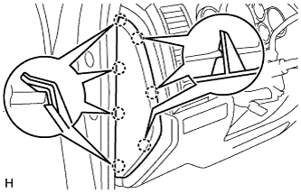 |
Attach the 7 claws to install the side panel.
| 43. CONNECT CABLE TO NEGATIVE BATTERY TERMINAL |
| 44. CHECK SRS WARNING LIGHT |
Check the SRS warning light (Click here).
| 45. INSPECT FOR EXHAUST GAS LEAK |
If gas is leaking, tighten the areas necessary to stop the leak. Replace damaged parts as necessary.