 |
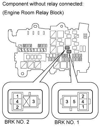
Remove the stop light control relays from the engine room relay block.
DTC C1311/12 Open or Short in Brake Inhibit Relay Circuit |
DTC C1380/64 Stop Light Control Relay Malfunction |
| DTC Code | DTC Detection Condition | Trouble Area |
| C1311/12 | Open or short circuit is detected. |
|
| C1380/64 | Open or short circuit is detected. |
|
| 1.CHECK TERMINAL VOLTAGE (STOP LIGHT CONTROL RELAY) |
|
Remove the stop light control relays from the engine room relay block.
Measure the voltage according to the value(s) in the table below.
| Tester Connection | Switch Condition | Specified Condition |
| Stop light control relay terminal 1 (BRK NO. 1) - Body ground | Ignition switch ON | 11 to 14 V |
| Stop light control relay terminal 1 (BRK NO. 2) - Body ground |
|
| ||||
| OK | |
 |
| 2.INSPECT STOP LIGHT CONTROL RELAY (BRK NO. 1, BRK NO. 2) |
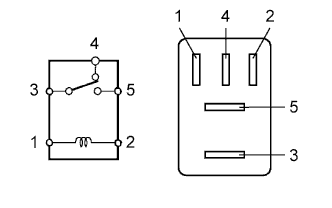 |
Remove the stop light control relays (BRK NO. 1 and BRK NO. 2) from the engine room relay block.
Measure the resistance according to the value(s) in the table below.
| Tester Connection | Condition | Specified Condition |
| 3 - 4 | When battery voltage is not applied to terminals 1 and 2 | Below 1 Ω |
| 3 - 5 | When battery voltage is not applied to terminals 1 and 2 | 10 kΩ or higher |
| 3 - 4 | When battery voltage is applied to terminals 1 and 2 | 10 kΩ or higher |
| 3 - 5 | When battery voltage is applied to terminals 1 and 2 | Below 1 Ω |
| Tester Connection | Condition | Specified Condition |
| 3 - 4 | When battery voltage is not applied to terminals 1 and 2 | Below 1 Ω |
| When battery voltage is applied to terminals 1 and 2 | 10 kΩ or higher |
|
| ||||
| OK | |
|
| 3.CHECK HARNESS AND CONNECTOR (BATTERY - SKID CONTROL ECU) |
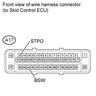 |
Disconnect the A17 ECU connector.
Measure the voltage according to the value(s) in the table below.
| Tester Connection | Switch Condition | Specified Condition |
| A17-44 (BSW) - Body ground | Ignition switch ON | 11 to 14 V |
| A17-15 (STPO) - Body ground | Ignition switch ON | 11 to 14 V |
|
| ||||
| OK | ||
 | ||
| ||
