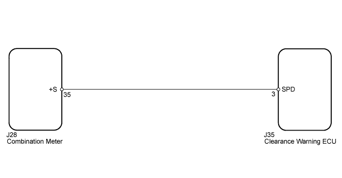
INTUITIVE PARKING ASSIST SYSTEM > Vehicle Speed Signal Circuit |
| 1.CHECK COMBINATION METER ASSEMBLY (SPEED SIGNAL) |
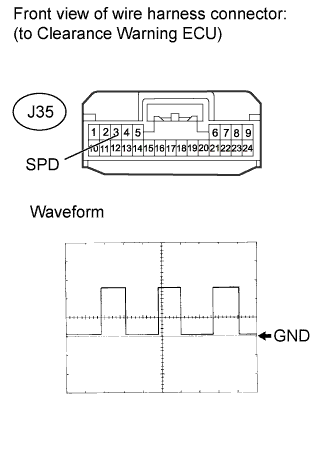 |
Disconnect the J35 ECU connector.
Using an oscilloscope, check the signal waveform of the meter.
| Item | Content |
| Terminal No. (Symbol) | J35-3 (SPD) - Body ground |
| Tool Setting | 5 V/DIV., 20 msec./DIV. |
| Condition | Drive vehicle at 20 km/h (12 mph) |
|
| ||||
| OK | ||
 | ||
| ||
| 2.CHECK HARNESS AND CONNECTOR (CLEARANCE WARNING ECU - COMBINATION METER) |
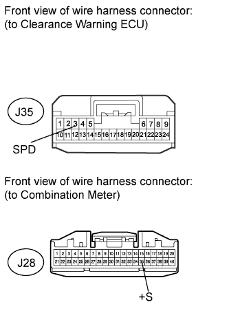 |
Disconnect the J35 clearance warning ECU connector.
Disconnect the J28 combination meter connector.
Measure the resistance according to the value(s) in the table below.
| Tester Connection | Condition | Specified Condition |
| J35-3 (SPD) - J28-35 (+S) | Always | Below 1 Ω |
| J35-3 (SPD) - Body ground | Always | 10 kΩ or higher |
|
| ||||
| OK | ||
| ||
| ||

