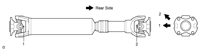
FRONT PROPELLER SHAFT ASSEMBLY > REASSEMBLY |
| 1. INSTALL FRONT PROPELLER SHAFT UNIVERSAL JOINT SPIDER BEARING |
|
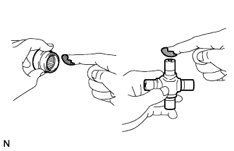
Apply MP grease to a new spider and bearings.
Fit the spider to the yoke.
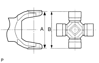 |
Measure dimension A between the snap ring grooves.
Insert the spider bearing into the spider journal portion, and then measure dimension B of the universal joint.
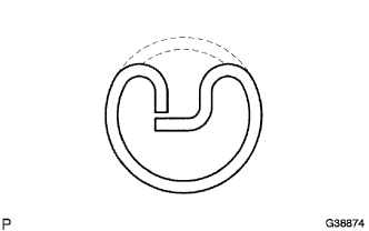 |
Select snap rings to make dimensions A and B the same.
| Color | Thickness |
| Green | 1.403 mm (0.0552 in.) |
| Black | 1.486 mm (0.0585 in.) |
| Copper | 1.512 mm (0.0595 in.) |
| White | 1.556 mm (0.0613 in.) |
| Yellow | 1.607 mm (0.0633 in.) |
| Blue | 1.657 mm (0.0652 in.) |
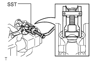 |
Insert the spider into the flange yoke, and then using SST, press in the spider bearing into the snap ring groove.
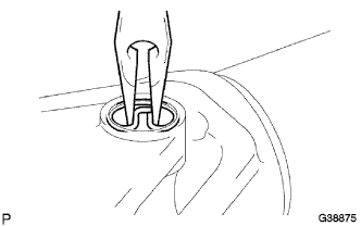 |
Using needle-nose pliers, install new snap rings into the grooves of the yoke.
| 2. INSPECT FRONT PROPELLER SHAFT UNIVERSAL JOINT SPIDER BEARING |
Check that the joints move smoothly.
Check the spider bearings for wear and damage.
Check the spider bearing axial play by turning the yoke while holding the shaft tightly.
| 3. INSPECT FRONT PROPELLER SHAFT ASSEMBLY |