Home › COMMUNICATION SYSTEM › CAN COMMUNICATION › CAN COMMUNICATION SYSTEM

CAN COMMUNICATION SYSTEM > TERMINALS OF ECU

for Preparation Click here


HINT:
Operating the ignition switch, any switches or any doors triggers related ECU and sensor communication with the CAN, which causes resistance variation.


DISCONNECT CABLE FROM NEGATIVE BATTERY TERMINAL
  1. Disconnect the cable from the negative (-) battery terminal before measuring the resistances of the main wire and the branch wire.

    CAUTION:
    Wait at least 90 seconds after disconnecting the cable from the negative (-) battery terminal to prevent airbag and seat belt pretensioner activation.

    NOTICE:
    1. Before measuring the resistance, leave the vehicle for at least 1 minute and do not operate the ignition switch, any switches or doors. If doors need to be opened in order to check connectors, open the doors and leave them open.
    2. After turning the ignition switch off, waiting time may be required before disconnecting the cable from the battery terminal. Therefore, make sure to read the disconnecting the cable from the battery terminal notice before proceeding with work (Click here).


JUNCTION CONNECTOR


  1. NO. 1 JUNCTION CONNECTOR
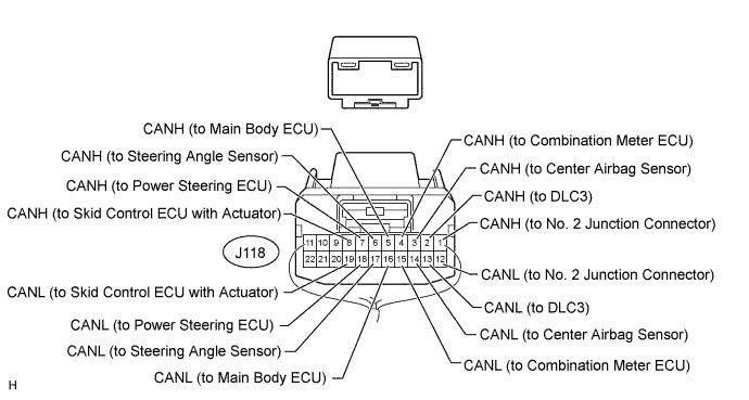

    C226742E02


    No. 1 Junction Connector
    Wiring Color
    Connected for
    J118-1 (CANH)
    R
    No. 2 junction connector
    J118-12 (CANL)
    W
    J118-2 (CANH)
    V
    DLC3
    J118-13 (CANL)
    W
    J118-3 (CANH)
    BR
    Center airbag sensor
    J118-14 (CANL)
    W
    J118-4 (CANH)*1
    SB
    Combination meter ECU
    J118-15 (CANL)*1
    W
    J118-5 (CANH)*1
    L
    Main body ECU
    J118-16 (CANL)*1
    W
    J118-6 (CANH)
    G
    Steering angle sensor
    J118-17 (CANL)
    W
    J118-7 (CANH)*2
    GR
    Power steering ECU
    J118-18 (CANL)*2
    W
    J118-8 (CANH)
    B
    Skid control ECU with actuator
    J118-19 (CANL)
    W

    HINT:
    1. *1: for V bus
    2. *2: w/ Power Steering ECU


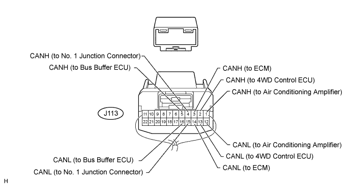
  2. NO. 2 JUNCTION CONNECTOR


    C172982E77


    No. 2 Junction Connector
    Wiring Color
    Connected for
    J113-1 (CANH)
    B
    Air conditioning amplifier
    J113-12 (CANL)
    W
    J113-2 (CANH)*1
    BE
    4WD control ECU
    J113-13 (CANL)*1
    W
    J113-3 (CANH)
    GR
    ECM
    J113-14 (CANL)
    W
    J113-4 (CANH)
    R
    No. 1 junction connector
    J113-15 (CANL)
    W
    J113-5 (CANH)*2
    P
    Bus buffer ECU
    J113-16 (CANL)*2
    W

    HINT:
    1. *1: w/ 4WD
    2. *2: w/ Bus Buffer ECU


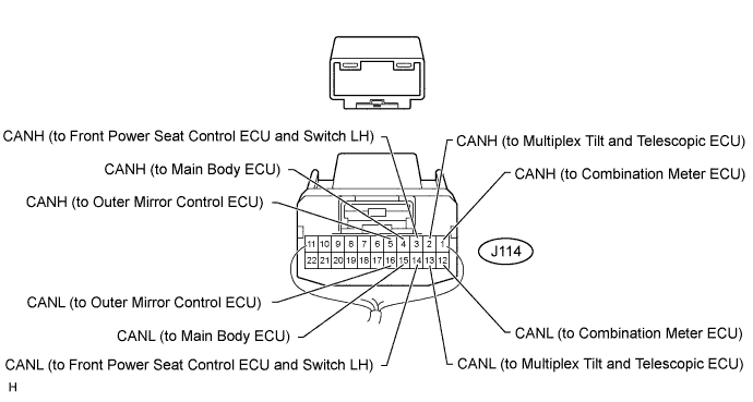
  3. NO. 3 JUNCTION CONNECTOR


    C172982E78


    No. 3 Junction Connector
    Wiring Color
    Connected for
    J114-1 (CANH)*1, *2
    Y
    Combination meter ECU
    J114-12 (CANL)*1, *2
    W
    J114-2 (CANH)*2
    BE
    Multiplex tilt and telescopic ECU
    J114-13 (CANL)*2
    W
    J114-3 (CANH)*2
    GR
    Front power seat control ECU and switch LH
    J114-14 (CANL)*2
    W
    J114-4 (CANH)*1, *2
    B
    Main body ECU
    J114-15 (CANL)*1, *2
    W
    J114-5 (CANH)*2
    LG
    Outer mirror control ECU
    J114-16 (CANL)*2
    W

    HINT:
    1. *1: for MS bus
    2. *2: w/ Seat Memory


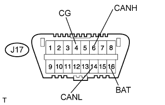
CHECK DLC3
H102392E69
  1. Measure the resistance according to the value(s) in the table below.

    Terminal No. (Symbols)
    Wiring Color
    Switch Condition
    Specified Condition
    J17-6 (CANH) - J17-14 (CANL)
    V - W
    Ignition switch OFF
    54 to 69 Ω
    J17-6 (CANH) - J17-4 (CG)
    V - W-B
    Ignition switch OFF
    200 Ω or higher
    J17-14 (CANL) - J17-4 (CG)
    W - W-B
    Ignition switch OFF
    200 Ω or higher
    J17-6 (CANH) - J17-16 (BAT)
    V - P
    Ignition switch OFF
    6 kΩ or higher
    J17-14 (CANL) - J17-16 (BAT)
    W - P
    Ignition switch OFF
    6 kΩ or higher


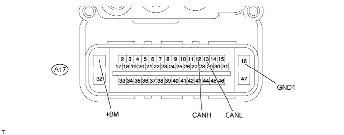
CHECK SKID CONTROL ECU WITH ACTUATOR

C240485E02

  1. Disconnect the A17 skid control ECU with actuator connector.

  2. Measure the resistance according to the value(s) in the table below.

    Terminal No. (Symbols)
    Wiring Color
    Switch Condition
    Specified Condition
    A17-12 (CANH) - A17-13 (CANL)
    B - W
    Ignition switch OFF
    54 to 69 Ω
    A17-12 (CANH) - A17-16 (GND1)
    B - W-B
    Ignition switch OFF
    200 Ω or higher
    A17-13 (CANL) - A17-16 (GND1)
    W - W-B
    Ignition switch OFF
    200 Ω or higher
    A17-12 (CANH) - A17-1 (+BM)
    B - L
    Ignition switch OFF
    6 kΩ or higher
    A17-13 (CANL) - A17-1 (+BM)
    W - L
    Ignition switch OFF
    6 kΩ or higher


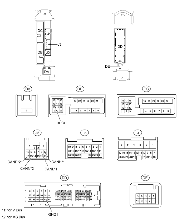
CHECK MAIN BODY ECU

E146976E03

  1. Disconnect the J2, DB and DD main body ECU connectors.

  2. Measure the resistance according to the value(s) in the table below.

    Terminal No. (Symbols)
    Wiring Color
    Switch Condition
    Specified Condition
    J2-5 (CANH) - J2-6 (CANL)*1
    L - W
    Ignition switch OFF
    54 to 69 Ω
    J2-5 (CANH) - DD-62 (GND1)*1
    L - W-B
    Ignition switch OFF
    200 Ω or higher
    J2-6 (CANL) - DD-62 (GND1)*1
    W - W-B
    Ignition switch OFF
    200 Ω or higher
    J2-5 (CANH) - DB-13 (BECU)*1
    L - GR
    Ignition switch OFF
    6 kΩ or higher
    J2-6 (CANL) - DB-13 (BECU)*1
    W - GR
    Ignition switch OFF
    6 kΩ or higher
    J2-16 (CANP) - J2-15 (CANN)*2
    B - W
    Ignition switch OFF
    108 to 132 Ω
    J2-16 (CANP) - DD-62 (GND1)*2
    B - W-B
    Ignition switch OFF
    200 Ω or higher
    J2-15 (CANN) - DD-62 (GND1)*2
    W - W-B
    Ignition switch OFF
    200 Ω or higher
    J2-16 (CANP) - DB-13 (BECU)*2
    B - GR
    Ignition switch OFF
    6 kΩ or higher
    J2-15 (CANN) - DB-13 (BECU)*2
    W - GR
    Ignition switch OFF
    6 kΩ or higher

    HINT:
    1. *1: for V bus
    2. *2: for MS bus


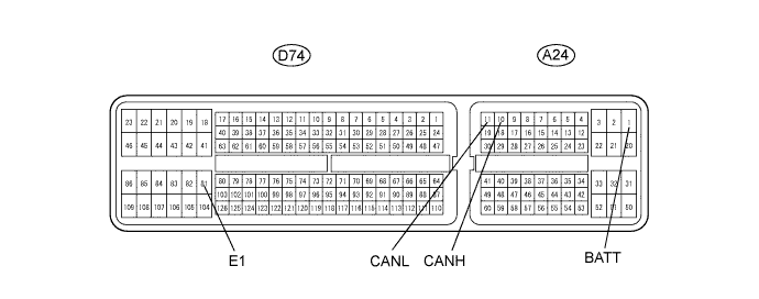
CHECK ECM

C159489E27

  1. Disconnect the A24 and D74 ECM connectors.

  2. Measure the resistance according to the value(s) in the table below.

    Terminal No. (Symbols)
    Wiring Color
    Switch Condition
    Specified Condition
    A24-10 (CANH) - A24-11 (CANL)
    GR - W
    Ignition switch OFF
    108 to 132 Ω
    A24-10 (CANH) - D74-81 (E1)
    GR - BR
    Ignition switch OFF
    200 Ω or higher
    A24-11 (CANL) - D74-81 (E1)
    W - BR
    Ignition switch OFF
    200 Ω or higher
    A24-10 (CANH) - A24-1 (BATT)
    GR - L
    Ignition switch OFF
    6 kΩ or higher
    A24-11 (CANL) - A24-1 (BATT)
    W - L
    Ignition switch OFF
    6 kΩ or higher


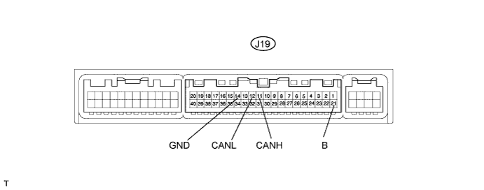
CHECK AIR CONDITIONING AMPLIFIER

C159478E01

  1. Disconnect the J19 air conditioning amplifier connector.

  2. Measure the resistance according to the value(s) in the table below.

    Terminal No. (Symbols)
    Wiring Color
    Switch Condition
    Specified Condition
    J19-11 (CANH) - J19-12 (CANL)
    B - W
    Ignition switch OFF
    54 to 69 Ω
    J19-11 (CANH) - J19-14 (GND)
    B - W-B
    Ignition switch OFF
    200 Ω or higher
    J19-12 (CANL) - J19-14 (GND)
    W - W-B
    Ignition switch OFF
    200 Ω or higher
    J19-11 (CANH) - J19-21 (B)
    B - R
    Ignition switch OFF
    6 kΩ or higher
    J19-12 (CANL) - J19-21 (B)
    W - R
    Ignition switch OFF
    6 kΩ or higher


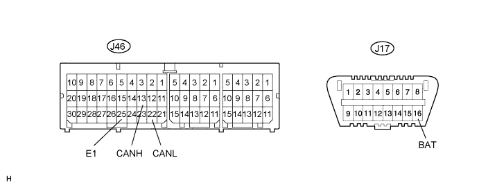
CHECK CENTER AIRBAG SENSOR

C162022E01

  1. Disconnect the J46 center airbag sensor connector.

  2. Measure the resistance according to the value(s) in the table below.

    Terminal No. (Symbols)
    Wiring Color
    Switch Condition
    Specified Condition
    J46-13 (CANH) - J46-22 (CANL)
    BR - W
    Ignition switch OFF
    54 to 69 Ω
    J46-13 (CANH) - J46-25 (E1)
    BR - W-B
    Ignition switch OFF
    200 Ω or higher
    J46-22 (CANL) - J46-25 (E1)
    W - W-B
    Ignition switch OFF
    200 Ω or higher
    J46-13 (CANH) - J17-16 (BAT)
    BR - P
    Ignition switch OFF
    6 kΩ or higher
    J46-22 (CANL) - J17-16 (BAT)
    W - P
    Ignition switch OFF
    6 kΩ or higher


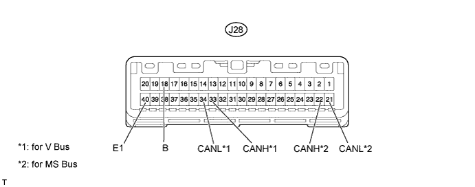
CHECK COMBINATION METER ECU

C159488E03

  1. Disconnect the J28 combination meter ECU connector.

  2. Measure the resistance according to the value(s) in the table below.

    Terminal No. (Symbols)
    Wiring Color
    Switch Condition
    Specified Condition
    J28-33 (CANH) - J28-34 (CANL)*1
    SB - W
    Ignition switch OFF
    108 to 132 Ω
    J28-33 (CANH) - J28-40 (E1)*1
    SB - W-B
    Ignition switch OFF
    200 Ω or higher
    J28-34 (CANL) - J28-40 (E1)*1
    W - W-B
    Ignition switch OFF
    200 Ω or higher
    J28-33 (CANH) - J28-18 (B)*1
    SB - LG
    Ignition switch OFF
    6 kΩ or higher
    J28-34 (CANL) - J28-18 (B)*1
    W - LG
    Ignition switch OFF
    6 kΩ or higher
    J28-22 (CANH) - J28-21 (CANL)*2
    Y - W
    Ignition switch OFF
    108 to 132 Ω
    J28-22 (CANH) - J28-40 (E1)*2
    Y - W-B
    Ignition switch OFF
    200 Ω or higher
    J28-21 (CANL) - J28-40 (E1)*2
    W - W-B
    Ignition switch OFF
    200 Ω or higher
    J28-22 (CANH) - J28-18 (B)*2
    Y - LG
    Ignition switch OFF
    6 kΩ or higher
    J28-21 (CANL) - J28-18 (B)*2
    W - LG
    Ignition switch OFF
    6 kΩ or higher

    HINT:
    1. *1: for V bus
    2. *2: for MS bus


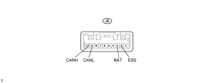
CHECK STEERING ANGLE SENSOR

C159491E01

  1. Disconnect the J6 steering angle sensor connector.

  2. Measure the resistance according to the value(s) in the table below.

    Terminal No. (Symbols)
    Wiring Color
    Switch Condition
    Specified Condition
    J6-10 (CANH) - J6-9 (CANL)
    G - W
    Ignition switch OFF
    54 to 69 Ω
    J6-10 (CANH) - J6-2 (ESS)
    G - W-B
    Ignition switch OFF
    200 Ω or higher
    J6-9 (CANL) - J6-2 (ESS)
    W - W-B
    Ignition switch OFF
    200 Ω or higher
    J6-10 (CANH) - J6-3 (BAT)
    G - R
    Ignition switch OFF
    6 kΩ or higher
    J6-9 (CANL) - J6-3 (BAT)
    W - R
    Ignition switch OFF
    6 kΩ or higher


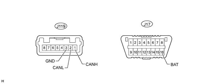
CHECK POWER STEERING ECU

HINT:
For vehicles with a power steering ECU only.


C226555E01

  1. Disconnect the J119 power steering ECU connector.

  2. Measure the resistance according to the value(s) in the table below.

    Terminal No. (Symbols)
    Wiring Color
    Switch Condition
    Specified Condition
    J119-1 (CANH) - J119-2 (CANL)
    GR - W
    Ignition switch OFF
    54 to 69 Ω
    J119-1 (CANH) - J119-3 (GND)
    GR - W-B
    Ignition switch OFF
    200 Ω or higher
    J119-2 (CANL) - J119-3 (GND)
    W - W-B
    Ignition switch OFF
    200 Ω or higher
    J119-1 (CANH) - J17-16 (BAT)
    GR - P
    Ignition switch OFF
    6 kΩ or higher
    J119-2 (CANL) - J17-16 (BAT)
    W - P
    Ignition switch OFF
    6 kΩ or higher


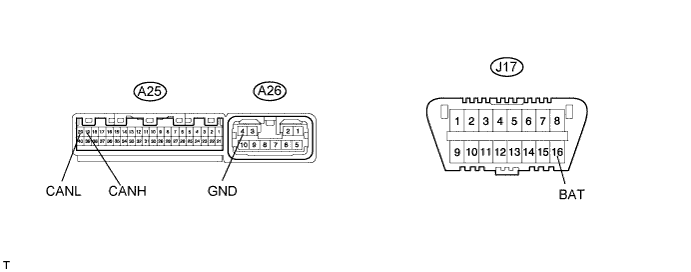
CHECK 4WD CONTROL ECU

HINT:
For vehicles with 4-wheel drive only.


C159479E01

  1. Disconnect the A25 and A26 4WD control ECU connectors.

  2. Measure the resistance according to the value(s) in the table below.

    Terminal No. (Symbols)
    Wiring Color
    Switch Condition
    Specified Condition
    A25-19 (CANH) - A25-20 (CANL)
    BE - W
    Ignition switch OFF
    54 to 69 Ω
    A25-19 (CANH) - A26-4 (GND)
    BE - W-B
    Ignition switch OFF
    200 Ω or higher
    A25-20 (CANL) - A26-4 (GND)
    W - W-B
    Ignition switch OFF
    200 Ω or higher
    A25-19 (CANH) - J17-16 (BAT)
    BE - P
    Ignition switch OFF
    6 kΩ or higher
    A25-20 (CANL) - J17-16 (BAT)
    W - P
    Ignition switch OFF
    6 kΩ or higher


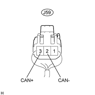
CHECK BUS BUFFER ECU
C159601E05

HINT:
For vehicles with a bus buffer ECU only.

  1. Disconnect the J59 bus buffer ECU connector.

  2. Measure the resistance according to the value(s) in the table below.

    Terminal No. (Symbols)
    Wiring Color
    Switch Condition
    Specified Condition
    J59-3 (CAN+) - J59-2 (CAN-)
    P - W
    Ignition switch OFF
    54 to 69 Ω


CHECK FRONT POWER SEAT CONTROL ECU AND SWITCH LH

HINT:
For vehicles with a front power seat control system (w/ Seat Memory) only.


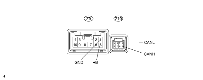
C159480E01

  1. Disconnect the Z9 and Z10 front power seat control ECU and switch LH connectors.

  2. Measure the resistance according to the value(s) in the table below.

    Terminal No. (Symbols)
    Wiring Color
    Switch Condition
    Specified Condition
    Z10-5 (CANH) - Z10-1 (CANL)
    GR - W
    Ignition switch OFF
    54 to 69 Ω
    Z10-5 (CANH) - Z9-1 (GND)
    GR - W-B
    Ignition switch OFF
    200 Ω or higher
    Z10-1 (CANL) - Z9-1 (GND)
    W - W-B
    Ignition switch OFF
    200 Ω or higher
    Z10-5 (CANH) - Z9-5 (+B)
    GR - L
    Ignition switch OFF
    6 kΩ or higher
    Z10-1 (CANL) - Z9-5 (+B)
    W - L
    Ignition switch OFF
    6 kΩ or higher


CHECK OUTER MIRROR CONTROL ECU

HINT:
For vehicles with a front power seat control system (w/ Seat Memory) only.


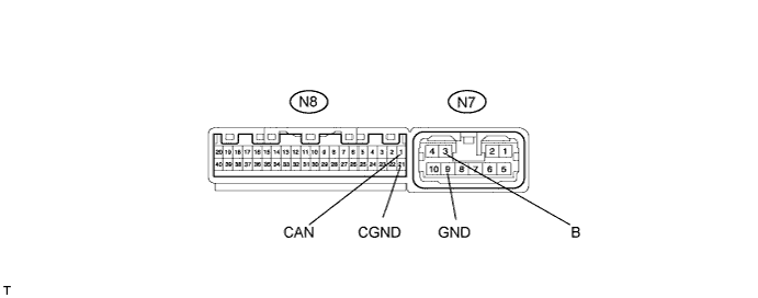
C159485E01

  1. Disconnect the N7 and N8 outer mirror control ECU connectors.

  2. Measure the resistance according to the value(s) in the table below.

    Terminal No. (Symbols)
    Wiring Color
    Switch Condition
    Specified Condition
    N8-1 (CAN) - N8-21 (CGND)
    LG - W
    Ignition switch OFF
    54 to 69 Ω
    N8-1 (CAN) - N7-9 (GND)
    LG - W-B
    Ignition switch OFF
    200 Ω or higher
    N8-21 (CGND) - N7-9 (GND)
    W - W-B
    Ignition switch OFF
    200 Ω or higher
    N8-1 (CAN) - N7-3 (B)
    LG - R
    Ignition switch OFF
    6 kΩ or higher
    N8-21 (CGND) - N7-3 (B)
    W - R
    Ignition switch OFF
    6 kΩ or higher


CHECK MULTIPLEX TILT AND TELESCOPIC ECU

HINT:
For vehicles with a front power seat control system (w/ Seat Memory) only.


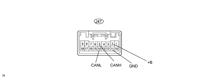
C159486E01

  1. Disconnect the J47 multiplex tilt and telescopic ECU connector.

  2. Measure the resistance according to the value(s) in the table below.

    Terminal No. (Symbols)
    Wiring Color
    Switch Condition
    Specified Condition
    J47-5 (CANH) - J47-14 (CANL)
    BE - W
    Ignition switch OFF
    54 to 69 Ω
    J47-5 (CANH) - J47-11 (GND)
    BE - W-B
    Ignition switch OFF
    200 Ω or higher
    J47-14 (CANL) - J47-11 (GND)
    W - W-B
    Ignition switch OFF
    200 Ω or higher
    J47-5 (CANH) - J47-2 (+B)
    BE - V
    Ignition switch OFF
    6 kΩ or higher
    J47-14 (CANL) - J47-2 (+B)
    W - V
    Ignition switch OFF
    6 kΩ or higher