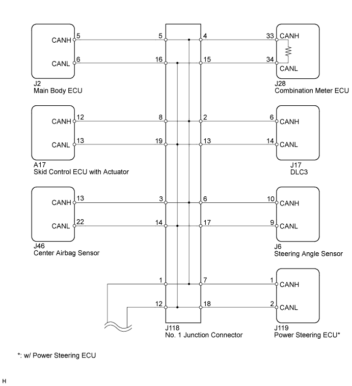
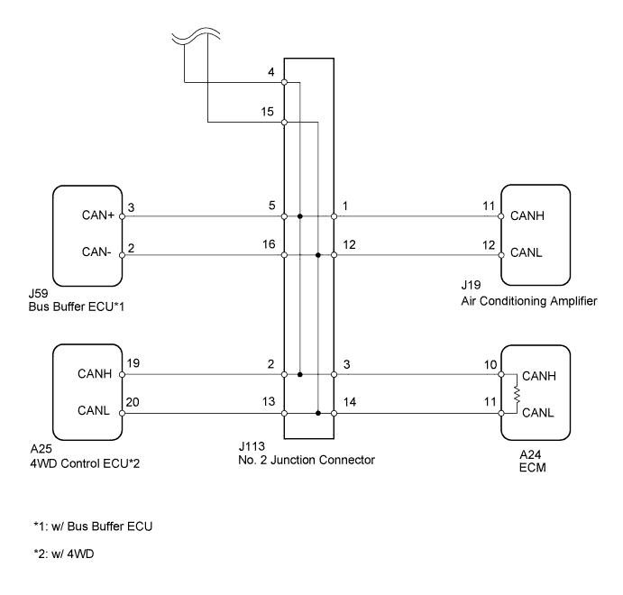
CAN COMMUNICATION SYSTEM > Open in One Side of CAN Branch Line |
| Symptom | Trouble Area |
| 2 or more ECUs and/or sensors do not appear on Techstream "CAN Bus Check" screen. |
|
| 1.CHECK FOR OPEN IN ONE SIDE OF CAN BRANCH WIRE (MAIN BODY ECU) |
Disconnect the J2 main body ECU connector.
Select "CAN Bus Check" on the Techstream.
| Result | Proceed to |
| "Main Body" is not displayed on the Techstream | A |
| Several ECUs and sensors in addition to "Main Body" are displayed on the Techstream | B |
|
| ||||
| A | |
 |
| 2.CHECK FOR OPEN IN ONE SIDE OF CAN BRANCH WIRE (MAIN BODY ECU BRANCH WIRE) |
Disconnect the cable from the negative (-) battery terminal before measuring the resistances of the main wire and the branch wire.
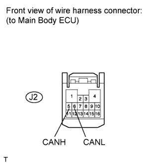 |
Measure the resistance according to the value(s) in the table below.
| Tester Connection | Switch Condition | Specified Condition |
| J2-5 (CANH) - J2-6 (CANL) | Ignition switch OFF | 54 to 69 Ω |
|
| ||||
| OK | ||
 | ||
| ||
| 3.CHECK FOR OPEN IN ONE SIDE OF CAN BRANCH WIRE (SKID CONTROL ECU WITH ACTUATOR) |
Disconnect the A17 skid control ECU with actuator connector.
Select "CAN Bus Check" on the Techstream.
| Result | Proceed to |
| "Skid Control (ABS/VSC/TRAC)" is not displayed on the Techstream | A |
| Several ECUs and sensors in addition to ""Skid Control (ABS/VSC/TRAC)" are displayed on the Techstream | B |
|
| ||||
| A | |
|
| 4.CHECK FOR OPEN IN ONE SIDE OF CAN BRANCH WIRE (SKID CONTROL ECU WITH ACTUATOR BRANCH WIRE) |
Disconnect the cable from the negative (-) battery terminal before measuring the resistances of the main wire and the branch wire.
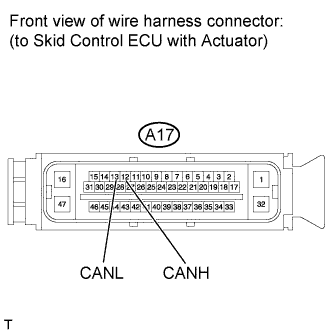 |
Measure the resistance according to the value(s) in the table below.
| Tester Connection | Switch Condition | Specified Condition |
| A17-12 (CANH) - A17-13 (CANL) | Ignition switch OFF | 54 to 69 Ω |
|
| ||||
| OK | ||
| ||
| ||
| 5.CHECK FOR OPEN IN ONE SIDE OF CAN BRANCH WIRE (STEERING ANGLE SENSOR) |
Disconnect the J6 steering angle sensor connector.
Select "CAN Bus Check" on the Techstream.
| Result | Proceed to |
| "Spiral cable (Steering Angle Sensor)" is not displayed on the Techstream | A |
| Several ECUs and sensors in addition to "Spiral cable (Steering Angle Sensor)" are displayed on the Techstream | B |
|
| ||||
| A | |
|
| 6.CHECK FOR OPEN IN ONE SIDE OF CAN BRANCH WIRE (STEERING ANGLE SENSOR BRANCH WIRE) |
Disconnect the cable from the negative (-) battery terminal before measuring the resistances of the main wire and the branch wire.
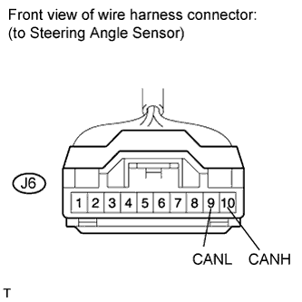 |
Measure the resistance according to the value(s) in the table below.
| Tester Connection | Switch Condition | Specified Condition |
| J6-10 (CANH) - J6-9 (CANL) | Ignition switch OFF | 54 to 69 Ω |
|
| ||||
| OK | ||
| ||
| ||
| 7.CHECK FOR OPEN IN ONE SIDE OF CAN BRANCH WIRE (BUS BUFFER ECU) |
Disconnect the J59 bus buffer ECU connector.
Select "CAN Bus Check" on the Techstream.
| Result | Proceed to |
| "Accessory Gateway" is not displayed on the Techstream | A |
| Several ECUs and sensors in addition to "Accessory Gateway" are displayed on the Techstream | B |
|
| ||||
| A | |
|
| 8.CHECK FOR OPEN IN ONE SIDE OF CAN BRANCH WIRE (BUS BUFFER ECU BRANCH WIRE) |
Disconnect the cable from the negative (-) battery terminal before measuring the resistances of the main wire and the branch wire.
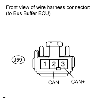 |
Measure the resistance according to the value(s) in the table below.
| Tester Connection | Switch Condition | Specified Condition |
| J59-3 (CAN+) - J59-2 (CAN-) | Ignition switch OFF | 54 to 69 Ω |
|
| ||||
| OK | ||
| ||
| ||
| 9.CHECK FOR OPEN IN ONE SIDE OF CAN BRANCH WIRE (CENTER AIRBAG SENSOR) |
Disconnect the J46 center airbag sensor connector.
Select "CAN Bus Check" on the Techstream.
| Result | Proceed to |
| "Airbag" is not displayed on the Techstream | A |
| Several ECUs and sensors in addition to "Airbag" are displayed on the Techstream | B |
|
| ||||
| A | |
|
| 10.CHECK FOR OPEN IN ONE SIDE OF CAN BRANCH WIRE (CENTER AIRBAG SENSOR BRANCH WIRE) |
Disconnect the cable from the negative (-) battery terminal before measuring the resistances of the main wire and the branch wire.
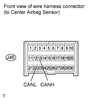 |
Measure the resistance according to the value(s) in the table below.
| Tester Connection | Switch Condition | Specified Condition |
| J46-13 (CANH) - J46-22 (CANL) | Ignition switch OFF | 54 to 69 Ω |
|
| ||||
| OK | ||
| ||
| ||
| 11.CHECK FOR OPEN IN ONE SIDE OF CAN BRANCH WIRE (4WD CONTROL ECU) |
Disconnect the A25 4WD control ECU connector.
Select "CAN Bus Check" on the Techstream.
| Result | Proceed to |
| "Four Wheel Drive Control" is not displayed on the Techstream | A |
| Several ECUs and sensors in addition to "Four Wheel Drive Control" are displayed on the Techstream | B |
|
| ||||
| A | |
|
| 12.CHECK FOR OPEN IN ONE SIDE OF CAN BRANCH WIRE (4WD CONTROL ECU BRANCH WIRE) |
Disconnect the cable from the negative (-) battery terminal before measuring the resistances of the main wire and the branch wire.
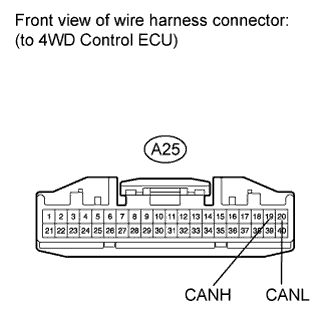 |
Measure the resistance according to the value(s) in the table below.
| Tester Connection | Switch Condition | Specified Condition |
| A25-19 (CANH) - A25-20 (CANL) | Ignition switch OFF | 54 to 69 Ω |
|
| ||||
| OK | ||
| ||
| ||
| 13.CHECK FOR OPEN IN ONE SIDE OF CAN BRANCH WIRE (POWER STEERING ECU) |
Disconnect the J119 power steering ECU connector.
Select "CAN Bus Check" on the Techstream.
| Result | Proceed to |
| "PPS" is not displayed on the Techstream | A |
| Several ECUs and sensors in addition to "PPS" are displayed on the Techstream | B |
|
| ||||
| OK | |
|
| 14.CHECK FOR OPEN IN ONE SIDE OF CAN BRANCH WIRE (POWER STEERING ECU BRANCH WIRE) |
Disconnect the cable from the negative (-) battery terminal before measuring the resistances of the main wire and the branch wire.
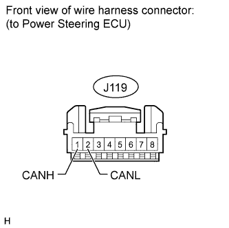 |
Measure the resistance according to the value(s) in the table below.
| Tester Connection | Switch Condition | Specified Condition |
| J119-1 (CANH) - J119-2 (CANL) | Ignition switch OFF | 54 to 69 Ω |
|
| ||||
| OK | ||
| ||
| ||
| 15.CHECK FOR OPEN IN ONE SIDE OF CAN BRANCH WIRE (AIR CONDITIONING AMPLIFIER BRANCH WIRE) |
Disconnect the cable from the negative (-) battery terminal before measuring the resistances of the main wire and the branch wire.
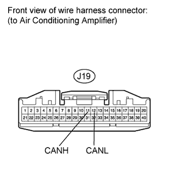 |
Disconnect the J19 air conditioning amplifier connector.
Measure the resistance according to the value(s) in the table below.
| Tester Connection | Switch Condition | Specified Condition |
| J19-11 (CANH) - J19-12 (CANL) | Ignition switch OFF | 54 to 69 Ω |
|
| ||||
| OK | ||
| ||
| ||

