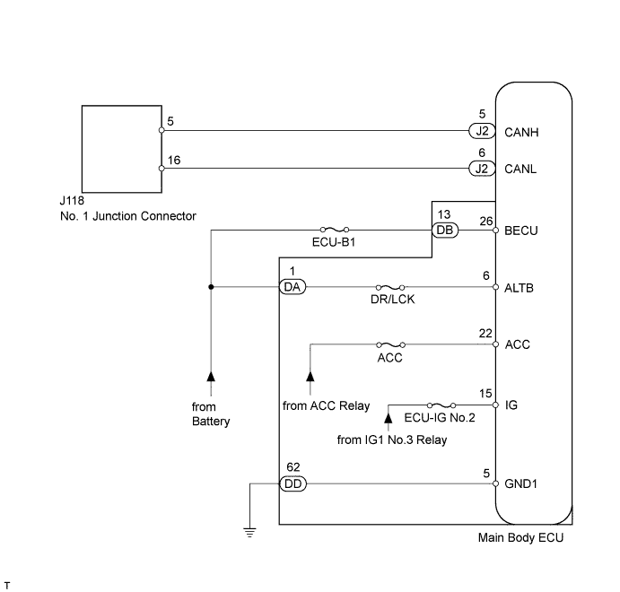
CAN COMMUNICATION SYSTEM > Main Body ECU Communication Stop Mode |
| Detection Item | Symptom | Trouble Area |
| Main Body ECU Communication Stop Mode | Either condition is met:
|
|
| 1.PRECAUTION |
| NEXT | |
 |
| 2.DISCONNECT CABLE FROM NEGATIVE BATTERY TERMINAL |
Disconnect the cable from the negative (-) battery terminal before measuring the resistances of the main wire and the branch wire.
| NEXT | |
|
| 3.CHECK FOR OPEN IN CAN BUS WIRE (MAIN BODY ECU BRANCH WIRE) |
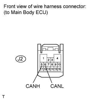 |
Disconnect the J2 main body ECU connector.
Measure the resistance according to the value(s) in the table below.
| Tester Connection | Switch Condition | Specified Condition |
| J2-5 (CANH) - J2-6 (CANL) | Ignition switch OFF | 54 to 69 Ω |
|
| ||||
| OK | |
|
| 4.CHECK HARNESS AND CONNECTOR (MAIN BODY ECU - BATTERY AND BODY GROUND) |
Reconnect the cable to the negative (-) battery terminal before measuring the resistances of the main wire and the branch wire.
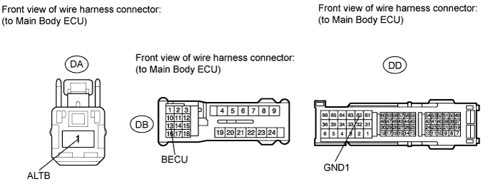
Disconnect the DA, DB and DD main body ECU connectors.
Measure the resistance according to the value(s) in the table below.
| Tester Connection | Condition | Specified Condition |
| DD-62 (GND1) - Body ground | Always | Below 1 Ω |
Measure the voltage according to the value(s) in the table below.
| Tester Connection | Condition | Specified Condition |
| DA-1 (ALTB) - Body ground | Always | 11 to 14 V |
| DB-13 (BECU) - Body ground | Always | 11 to 14 V |
|
| ||||
| OK | ||
 | ||
| ||
