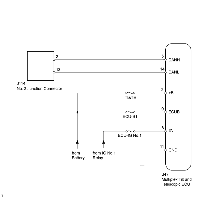
DTC U1115 Lost Communication with Tilt and Telescopic Module |
| DTC Code | DTC Detection Condition | Trouble Area |
| U1115 | No communication from multiplex tilt and telescopic ECU |
|
| 1.PRECAUTION |
| NEXT | |
 |
| 2.DISCONNECT CABLE FROM NEGATIVE BATTERY TERMINAL |
Disconnect the cable from the negative (-) battery terminal before measuring the resistances of the main wire and the branch wire.
| NEXT | |
|
| 3.CHECK FOR OPEN IN CAN BUS WIRE (MULTIPLEX TILT AND TELESCOPIC ECU BRANCH WIRE) |
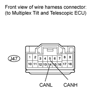 |
Disconnect the J47 multiplex tilt and telescopic ECU connector.
Measure the resistance according to the value(s) in the table below.
| Tester Connection | Switch Condition | Specified Condition |
| J47-5 (CANH) - J47-14 (CANL) | Ignition switch OFF | 54 to 69 Ω |
|
| ||||
| OK | |
|
| 4.CHECK HARNESS AND CONNECTOR (MULTIPLEX TILT AND TELESCOPIC ECU - BATTERY AND BODY GROUND) |
Reconnect the cable from the negative (-) battery terminal before measuring the resistances of the main wire and the branch wire.
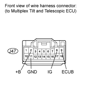 |
Measure the resistance according to the value(s) in the table below.
| Tester Connection | Condition | Specified Condition |
| J47-11 (GND) - Body ground | Always | Below 1 Ω |
Measure the voltage according to the value(s) in the table below.
| Tester Connection | Switch Condition | Specified Condition |
| J47-2 (+B) - Body ground | Always | 11 to 14 V |
| J47-9 (ECUB) - Body ground | Always | 11 to 14 V |
| J47-8 (IG) - Body ground | Ignition switch ON | 11 to 14 V |
|
| ||||
| OK | ||
 | ||
| ||
