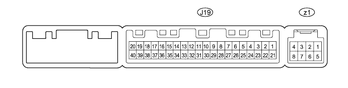
AIR CONDITIONING SYSTEM (for Automatic Air Conditioning System) > TERMINALS OF ECU |
| CHECK AIR CONDITIONING AMPLIFIER |
Measure the voltage and resistance according to the value(s) in the table below.
| Terminal No. (Symbols) | Wiring Color | Terminal Description | Condition | Specified Condition |
| J19-1 (IG+) - J19-14 (GND) | P - W-B | Ignition power supply | Ignition switch ON | 11 to 14 V |
| Ignition switch OFF | Below 1 V | |||
| J19-21 (B) - J19-14 (GND) | R - W-B | Battery power source | Always | 11 to 14 V |
| J19-14 (GND) - Body ground | W-B - Body ground | Ground | Always | Below 1 Ω |
| J19-5 (TAM) - J19-14 (GND) | V - W-B | A/C ambient temperature sensor signal | Ignition switch ON at 25°C (77°F) | 1.35 to 1.75 V |
| J19-5 (TAM) - J19-14 (GND) | V - W-B | A/C ambient temperature sensor signal | Ignition switch ON at 40°C (104°F) | 0.9 to 1.2 V |
| J19-8 (LOCK) - J19-14 (GND) | SB - W-B | A/C compressor lock sensor signal | Engine is running Blower switch LO A/C switch ON | Pulse generation (see waveform 1) |
| J19-23 (BLW) - J19-14 (GND) | LG - W-B | Blower motor control signal | Ignition switch ON Blower switch LO | Pulse generation (see waveform 2) |
| J19-20 (MGC) - J19-14 (GND) | P - W-B | A/C compressor magnetic clutch operation signal | Ignition switch ON Blower switch LO A/C switch OFF | 11 to 14 V |
| J19-20 (MGC) - J19-14 (GND) | P - W-B | A/C compressor magnetic clutch operation signal | Ignition switch ON Blower switch LO A/C switch ON | Below 1 V |
| J19-33 (TSD) - J19-14 (GND) | P - W-B | Driver side solar sensor signal | Ignition switch ON Solar sensor subjected to electric light | 0.8 to 4.3 V |
| J19-32 (TSP) - J19-14 (GND) | L - W-B | Passenger side solar sensor signal | Ignition switch ON Solar sensor subjected to electric light | 0.8 to 4.3 V |
| J19-29 (TR) - J19-34 (SG-1) | G - B | Room temperature sensor signal | Ignition switch ON Front side interior temperature: 25°C (77°F) | 1.8 to 2.2 V |
| J19-34 (SG-1) - Body ground | B - Body ground | Ground for room temperature sensor | Always | Below 1 Ω |
| J19-13 (SG-2) - Body ground | G - Body ground | Ground for ambient temperature sensor | Always | Below 1 Ω |
| J19-37 (LIN1) - J19-14 (GND) | SB - W-B | LIN communication signal | Ignition switch ON | Pulse generation |
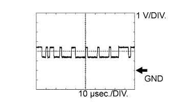
| J19-11 (CANH) - J19-14 (GND) | B - W-B | Hi-level CAN bus line | Ignition switch ON | Pulse generation (see waveform 3) |
| J19-12 (CANL) - J19-14 (GND) | W - W-B | Lo-level CAN bus line | Ignition switch ON | Pulse generation (see waveform 4) |
| z1-2 (BUS G) - Body ground | - | Ground for BUS IC | Always | Below 2 V |
| z1-3 (BUS) - z1-2 (BUS G) | - | BUS IC control signal | Ignition switch OFF → ON | Pulse generation |
| z1-4 (B BUS) - z1-2 (BUS G) | - | Power supply for BUS IC | Always | 11 to 14 V |
| z1-5 (SGA) - Body ground | - | Ground for evaporator temperature sensor | Always | Below 2 V |
| z1-6 (TEA) - z1-5 (SGA) | - | A/C evaporator temperature sensor signal | Ignition switch ON Evaporator temperature at 0°C (32°F) | 1.7 to 2.1 V |
| z1-6 (TEA) - z1-5 (SGA) | - | A/C evaporator temperature sensor signal | Ignition switch ON Evaporator temperature at 15°C (59°F) | 0.7 to 1.3 V |
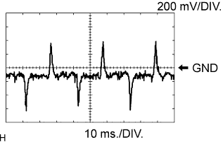 |
Using an oscilloscope, check waveform 1.
| Terminal No. (Symbols) | Tool Setting | Condition |
| J19-8 (LOCK) - J19-14 (GND) | 200 mV/DIV., 10 ms./DIV. | Engine is running Blower switch LO A/C switch ON |
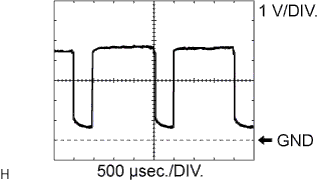 |
Using an oscilloscope, check waveform 2.
| Terminal No. (Symbols) | Tool Setting | Condition |
| J19-23 (BLW) - J19-14 (GND) | 1 V/DIV., 500 μsec./DIV. | Ignition switch ON Blower switch LO |
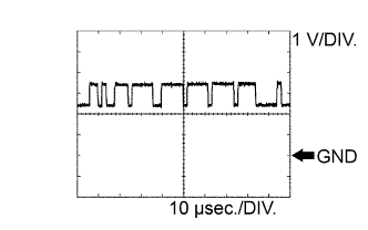 |
Using an oscilloscope, check waveform 3.
| Terminal No. (Symbols) | Tool Setting | Condition |
| J19-11 (CANH) - J19-14 (GND) | 1 V/DIV., 10 μsec./DIV. | Ignition switch ON |
 |
Using an oscilloscope, check waveform 4.
| Terminal No. (Symbols) | Tool Setting | Condition |
| J19-12 (CANL) - J19-14 (GND) | 1 V/DIV., 10 μsec./DIV. | Ignition switch ON |
| CHECK INTEGRATION CONTROL AND PANEL |

Disconnect the J37 integration control and panel connector.
Measure the voltage and resistance according to the value(s) in the table below.
| Terminal No. (Symbols) | Wiring Color | Terminal Description | Condition | Specified Condition |
| J37-16 (IG+) - J37-1 (GND) | P - W-B | Ignition power supply | Ignition switch ON | 11 to 14 V |
| Ignition switch OFF | Below 1 V | |||
| J37-1 (GND) - Body ground | W-B - Body ground | Ground | Always | Below 1 Ω |
| J37-3 (STX) - J37-1 (GND) | SB - W-B | LIN communication signal | Ignition switch ON | Pulse generation |