Detach the claw and remove the front pillar garnish.
AIR CONDITIONING PANEL (for Column Shift Type) > REMOVAL |
| 1. PRECAUTION |
| 2. DISCONNECT CABLE FROM NEGATIVE BATTERY TERMINAL |
| 3. REMOVE FRONT DOOR SCUFF PLATE LH |
for Regular Cab:
Remove the front door scuff plate .
for Double Cab:
Remove the front door scuff plate .
for CrewMax:
Remove the front door scuff plate .
| 4. REMOVE COWL SIDE TRIM BOARD LH |
for Regular Cab:
Remove the cowl side trim board .
for Double Cab:
Remove the cowl side trim board .
for CrewMax:
Remove the cowl side trim board .
| 5. REMOVE FRONT DOOR OPENING TRIM WEATHERSTRIP LH (for Regular Cab) |
Remove the front door opening trim weatherstrip.
| 6. REMOVE FRONT DOOR OPENING TRIM WEATHERSTRIP LH (for Double cab, CrewMax) |
Remove the front door opening trim weatherstrip.
| 7. REMOVE FRONT PILLAR GARNISH LH |
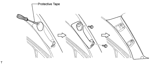
Using a screwdriver, detach the 2 claws and remove the 2 assist grip plugs.
Remove the 2 bolts and assist grip.
Detach the claw and remove the front pillar garnish.
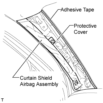 |
Protect the curtain shield airbag.
Thoroughly cover the airbag with a cloth or nylon sheet and fix the ends of the cover with adhesive tape, as shown in the illustration.
| 8. REMOVE CENTER LOWER INSTRUMENT COVER |
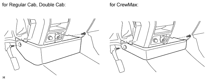
Remove the 2 clips and cover.
| 9. REMOVE INSTRUMENT SIDE PANEL LH |
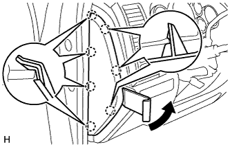 |
Using a moulding remover, detach the 7 claws and remove the side panel.
| 10. REMOVE LOWER INSTRUMENT PANEL FINISH PANEL SUB-ASSEMBLY LH |
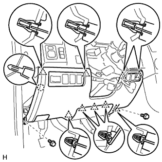 |
Remove the hood lock control lever.
Remove the 2 bolts.
Detach the 9 clips and claw.
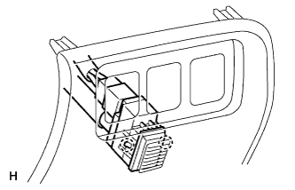 |
for Automatic Air Conditioning System:
Detach the 2 claws and remove the sensor.
Remove the finish panel and then disconnect the connectors.
| 11. REMOVE LOWER NO. 1 INSTRUMENT PANEL AIRBAG ASSEMBLY |
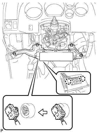 |
Remove the 4 bolts and remove the instrument panel airbag.
Detach the 2 claws and disconnect the DLC3.
Disconnect the connector.
| 12. REMOVE INSTRUMENT CLUSTER FINISH PANEL ASSEMBLY |
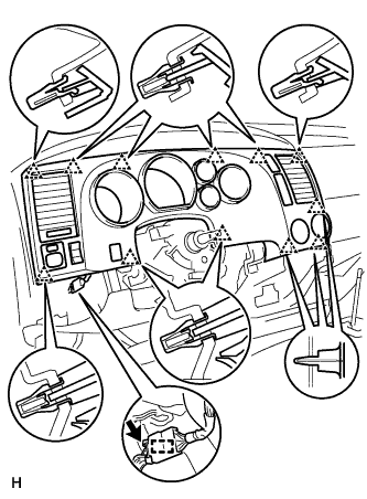 |
Disconnect the connector and detach the wire harness clamp.
Detach the 12 clips and remove the finish panel.
| 13. REMOVE LOWER INSTRUMENT CLUSTER FINISH PANEL |
|
Disconnect the connector and detach the wire harness clamp.
Detach the 12 clips and remove the finish panel.
| 14. REMOVE INSTRUMENT PANEL CUP HOLDER ASSEMBLY |
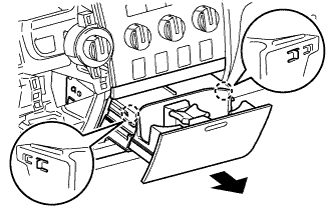 |
Detach the 2 claws and remove the door box.
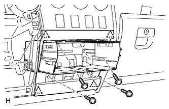 |
Remove the 4 screws.
Detach the 4 clips and remove the cup holder.
| 15. REMOVE INTEGRATION CONTROL AND PANEL ASSEMBLY |
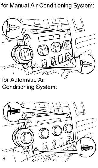 |
Detach the 4 clips.
Disconnect the connector and remove the panel.
| 16. REMOVE RADIO RECEIVER ASSEMBLY WITH BRACKET (w/o USB Audio System) |
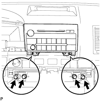 |
Remove the 4 bolts.
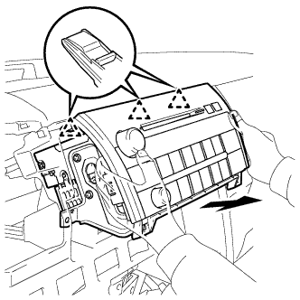 |
Pull the radio receiver to detach the 3 clips on the backside of the radio receiver.
Disconnect the connectors and remove the radio receiver.
| 17. REMOVE RADIO RECEIVER ASSEMBLY WITH BRACKET (w/ USB Audio System) |
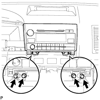 |
Remove the 4 bolts.
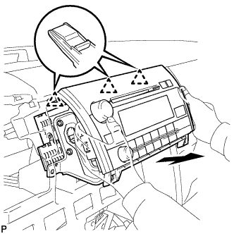 |
Pull the radio receiver to detach the 3 clips on the backside of the radio receiver.
Disconnect the connectors and remove the radio receiver.
| 18. REMOVE NAVIGATION RECEIVER ASSEMBLY WITH BRACKET (w/ Navigation System) |
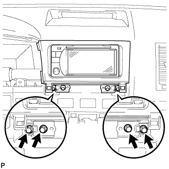 |
Remove the 4 bolts.
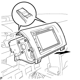 |
Pull the navigation receiver as shown in the illustration to detach the 2 clips on the backside of the navigation receiver.
Disconnect the connectors and remove the navigation receiver.