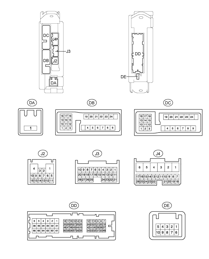
LIGHTING SYSTEM > TERMINALS OF ECU |
| CHECK MAIN BODY ECU |
Disconnect the J2, J3, J4, DA, DB, DC and DD ECU connectors.
Measure the voltage and resistance according to the value(s) in the table below.
| Terminal No. (Symbols) | Wiring Color | Terminal Description | Condition | Specified Condition |
| DB-13 (BECU) - Body ground | GR - Body ground | BECU power supply | Always | 11 to 14 V |
| DA-1 (ACC) - Body ground | B - Body ground | ACC power supply | Always | 11 to 14 V |
| DA-1 (IG) - Body ground | B - Body ground | IG power supply | Always | 11 to 14 V |
| DA-1 (TRLY) - Body ground | B - Body ground | Taillight power supply | Always | 11 to 14 V |
| DD-62 (GND1) - Body ground | W-B - Body ground | Body ground | Always | Below 1 Ω |
| DD-62 (GND2) - Body ground | W-B - Body ground | Body ground | Always | Below 1 Ω |
| J4-24 (DCTY) - Body ground | BR - Body ground | Front door courtesy light switch LH signal | Front door LH open | Below 1 Ω |
| J4-24 (DCTY) - Body ground | BR - Body ground | Front door courtesy light switch LH signal | Front door LH closed | 10 kΩ or higher |
| J3-21 (PCTY) - Body ground | BE - Body ground | Front door courtesy light switch RH signal | Front door RH open | Below 1 Ω |
| J3-21 (PCTY) - Body ground | BE - Body ground | Front door courtesy light switch RH signal | Front door RH closed | 10 kΩ or higher |
| DC-2 (LCTY) - Body ground | B - Body ground | Rear door courtesy light switch LH signal | Rear door LH open | Below 1 Ω |
| DC-2 (LCTY) - Body ground | B - Body ground | Rear door courtesy light switch LH signal | Rear door LH closed | 10 kΩ or higher |
| J3-25 (RRCY) - Body ground | L - Body ground | Rear door courtesy light switch RH signal | Rear door RH open | Below 1 Ω |
| J3-25 (RRCY) - Body ground | L - Body ground | Rear door courtesy light switch RH signal | Rear door RH closed | 10 kΩ or higher |
| J4-23 (TAIL) - Body ground | BE - Body ground | Light control switch TAIL signal | Light control switch TAIL | Below 1 Ω |
| J4-23 (TAIL) - Body ground | BE - Body ground | Light control switch TAIL signal | Light control switch except TAIL | 10 kΩ or higher |
| J3-17 (HEAD) - Body ground | W - Body ground | Light control switch HEAD signal | Light control switch HEAD | Below 1 Ω |
| J3-17 (HEAD) - Body ground | W - Body ground | Light control switch HEAD signal | Light control switch except HEAD | 10 kΩ or higher |
| J4-21 (A) - Body ground | G - Body ground | Light control switch AUTO signal | Light control switch AUTO | Below 1 Ω |
| J4-21 (A) - Body ground | G - Body ground | Light control switch AUTO signal | Light control switch except AUTO | 10 kΩ or higher |
| J3-28 (FFOG) - Body ground | P - Body ground | Front fog light switch signal | Front fog light switch on | Below 1 Ω |
| J3-28 (FFOG) - Body ground | P - Body ground | Front fog light switch signal | Front fog light switch off | 10 kΩ or higher |
| J2-4 (HAZ) - Body ground | BE - Body ground | Hazard warning signal switch input signal | Hazard warning signal switch on | Below 1 Ω |
| J2-4 (HAZ) - Body ground | BE - Body ground | Hazard warning signal switch input signal | Hazard warning signal switch off | 10 kΩ or higher |
| J3-9 (CGSW) - Body ground | BR - Body ground | Cargo light switch signal | Cargo light switch on | Below 1 Ω |
| J3-9 (CGSW) - Body ground | BR - Body ground | Cargo light switch signal | Cargo light switch DOOR | 10 kΩ or higher |
| J3-9 (CGSW) - Body ground | BR - Body ground | Cargo light switch signal | Cargo light switch off | 10 kΩ or higher |
Reconnect the J2, J3, J4, DA, DB, DC and DD ECU connectors.
Measure the voltage according to the value(s) in the table below.
| Terminal No. (Symbols) | Wiring Color | Terminal Description | Condition | Specified Condition |
| J4-4 (FFGO) - Body ground | SB - Body ground | Front fog light signal | Light control switch TAIL, front fog light switch on | Below 1 V |
| J4-4 (FFGO) - Body ground | SB - Body ground | Front fog light signal | Light control switch TAIL, front fog light switch off | 11 to 14 V |
| DB-18 (HRLY) - Body ground | L - Body ground | Headlight low beam signal | Light control switch HEAD, dimmer switch Low | Below 1 V |
| DB-18 (HRLY) - Body ground | L - Body ground | Headlight low beam signal | Light control switch HEAD, dimmer switch except Low | 11 to 14 V |
| DB-16 (DIM) - Body ground | R - Body ground | Headlight low beam signal | Light control switch HEAD, dimmer switch High | Below 1 V |
| DB-16 (DIM) - Body ground | R - Body ground | Headlight low beam signal | Light control switch HEAD, dimmer switch except High | 11 to 14 V |
| J2-14 (CGLP) - Body ground | LG - Body ground | Cargo light signal | Cargo light switch off | Below 1 V |
| J2-14 (CGLP) - Body ground | LG - Body ground | Cargo light signal | Cargo light switch DOOR, door is closed | 11 to 14 V |
| J2-14 (CGLP) - Body ground | LG - Body ground | Cargo light signal | Cargo light switch DOOR, door is open | Below 1 V |
| J2-14 (CGLP) - Body ground | LG - Body ground | Cargo light signal | Cargo light switch on | Below 1 V |