SHIFT LEVER ASSEMBLY (for Column Shift Type) > REASSEMBLY |
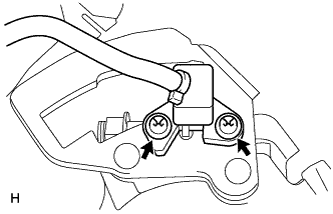
| 1. INSTALL TRANSMISSION CONTROL SWITCH (P POSITION) |
|
Install the switch to the column shift control shift lever retainer with the 2 screws.
| 2. INSTALL TRANSMISSION CONTROL SWITCH (S POSITION) |
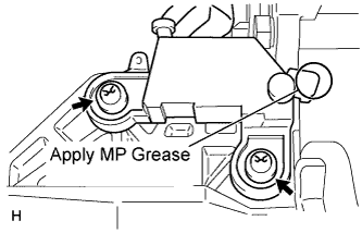 |
Apply MP grease to the switch shown in the illustration.
Install the switch to the column shift control shift lever retainer with the 2 screws.
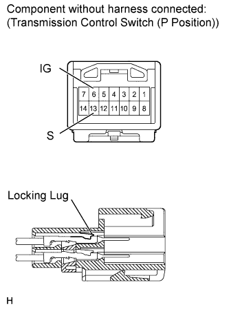 |
Securely connect the 2 wire terminals to terminal 6 (IG) and 13 (S) of the transmission control switch connector.
| 3. CONNECT NO. 1 SHIFT LOCK PLATE SUB-ASSEMBLY |
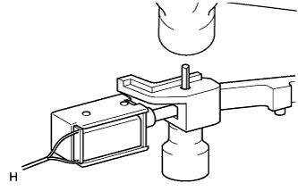 |
Using a hammer, tap in the spring pin to connect the shift lock plate and shift lock solenoid.
| 4. INSTALL SHIFT LOCK SOLENOID |
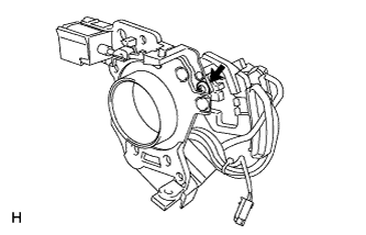 |
Install the shift lock solenoid with No. 1 shift lock plate sub-assembly, 2 bushes and collar to the column shift control shift lever retainer with the screw.
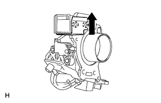 |
Attach the 2 claws to install the shift lock solenoid bracket.
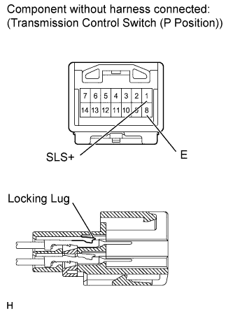 |
Securely connect the 2 wire terminals to terminal 1 (SLS+) and 8 (E) of the transmission control switch connector.
| 5. INSTALL COLUMN SHIFT SHIFT LEVER SUB-ASSEMBLY |
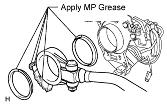 |
Apply MP grease to the 2 lever selecting bushes and shift lever shown in the illustration.
Install the 2 lever selecting bushes and shift lever to the column shift control shift lever retainer.
Pass the wire harness of the shift lever through the control shaft tube clamp.
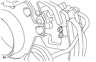 |
Attach the 2 claws to install the control shaft tube clamp to the column shift control shift lever retainer.
 |
w/o Trailer Towing System:
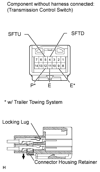
Securely connect the 3 wire terminals to terminal 4 (SFTD), 5 (SFTU) and 11 (E) of the transmission control switch connector. Then push the connector housing retainer to lock it.
w/ Trailer Towing System:
Securely connect the 4 wire terminals to terminal 4 (SFTD), 5 (SFTU), 12 (P), 9 (E) and 11 (E) of the transmission control switch connector. Then push the connector housing retainer to lock it.
Fix the connector housing retainer of the connector in place.
| 6. INSTALL COLUMN SHIFT SHIFT LOCK RELEASE LINK |
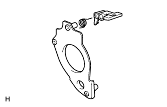 |
Install the spring and shift lock release link to the shift lever plate.
| 7. INSTALL SHIFT LEVER PLATE SUB-ASSEMBLY |
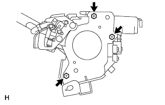 |
Install the shift lever plate to the column shift control shift lever retainer with the 3 bolts.
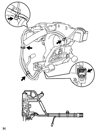 |
Clamp the harness with the 4 wire guides and wire harness clamp as shown in the illustration.
| 8. INSTALL COLUMN SHIFT LEVER COMPRESSION SPRING |
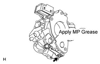 |
Apply MP grease to the spring shown in the illustration.
Temporarily install the spring to the column shift control shift lever retainer with the bolt.
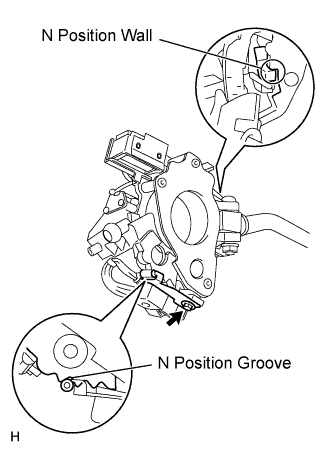 |
With the shift lever's protrusion pushed towards the column shift control shift lever retainer's N position wall, align the spring's roller to the groove as shown in the illustration. Then tighten the bolt.
| 9. INSTALL COLUMN SHIFT SHIFTING BELLCRANK ASSEMBLY |
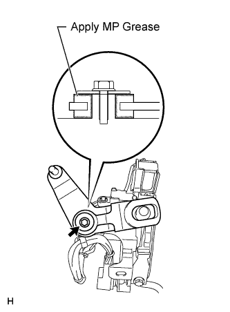 |
Apply MP grease to the shifting bellcrank shown in the illustration.
Install the shifting bellcrank with the bolt.