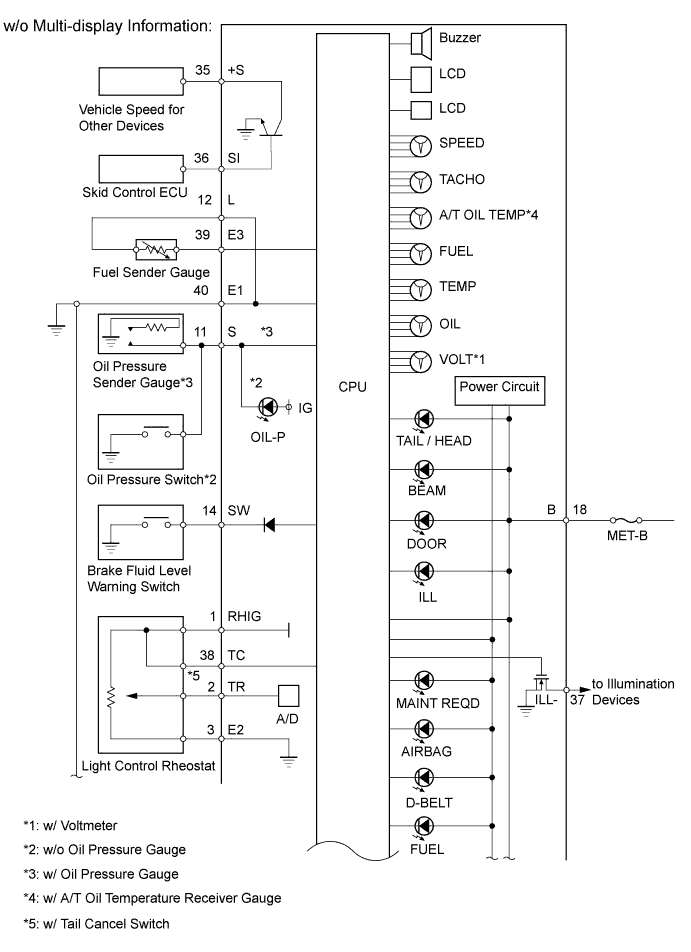
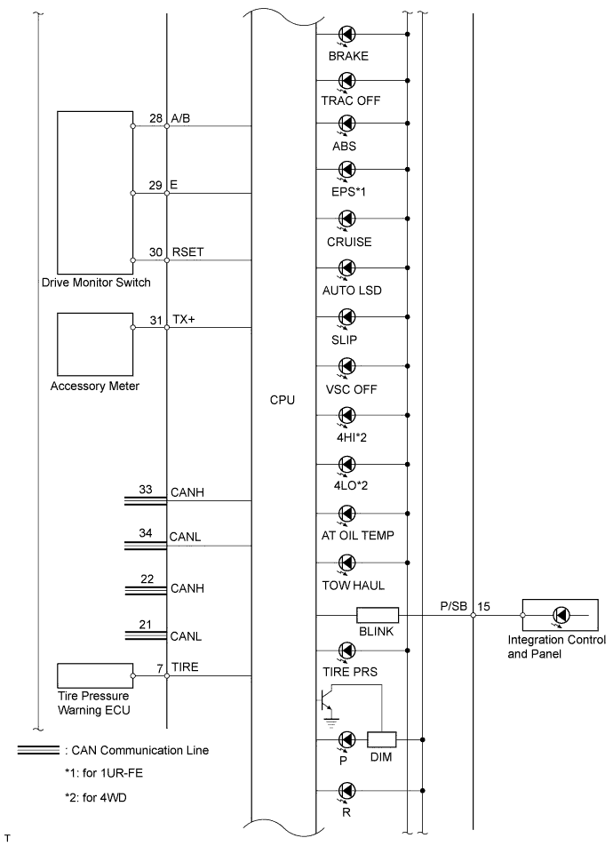
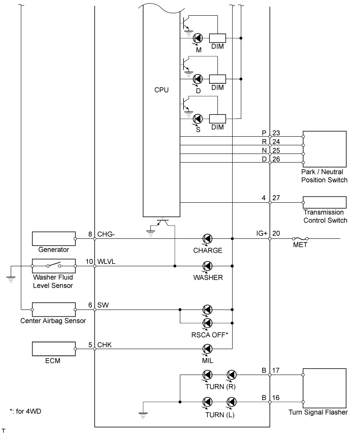
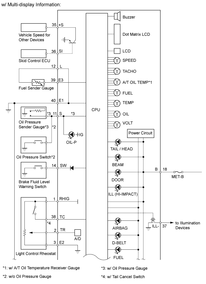
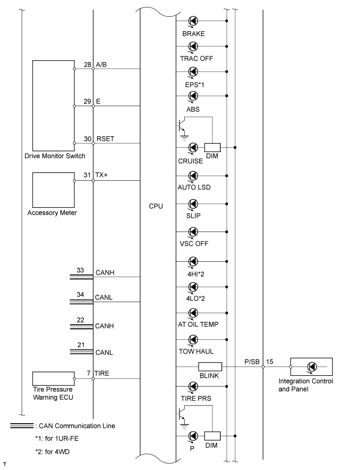
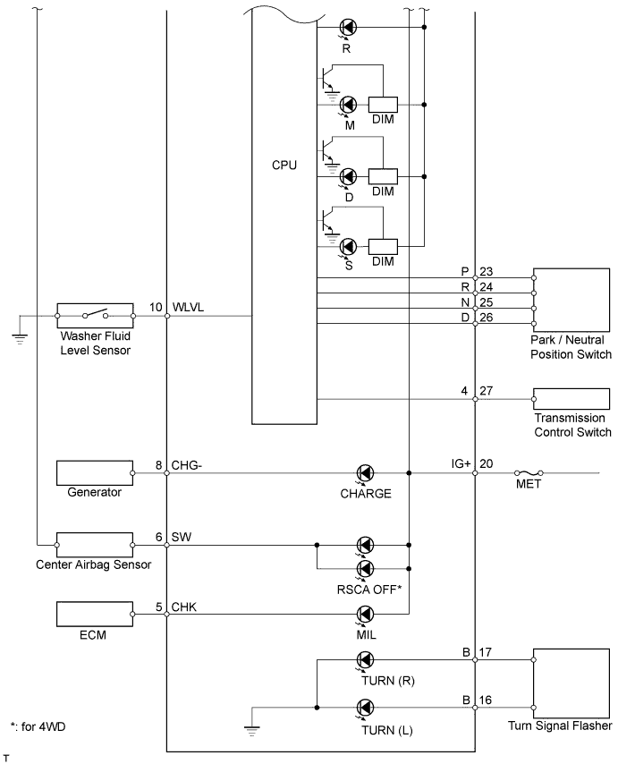
Terminal No. (Symbols)
| Wiring Color
| Terminal Description
| Condition
| Specified Condition
|
J28-1 (RHIG) - Body ground
| W - Body ground
| Power source for light control rheostat
| Ignition switch ON
| 4.6 to 5.4 V
|
J28-2 (TR) - Body ground
| LG - Body ground
| Light control rheostat knob input
| Light control rheostat knob fully turned downward
| Below 1 Ω
|
Light control rheostat knob fully turned upward
| 10 kΩ or higher
|
J28-3 (E2) - Body ground
| G - Body ground
| Light control rheostat switch ground
| Always
| Below 1 Ω
|
J28-5 (CHK) - Body ground
| R - Body ground
| MIL input signal
| Ignition switch ON, MIL ON
| Below 3 V
|
Ignition switch OFF, MIL OFF
| 11 to 14 V
|
J28-6 (SW) - Body ground*1
| Y - Body ground
| RSCA OFF indicator light input signal
| Ignition switch ON, RSCA OFF indicator light ON
| Below 1 V
|
Ignition switch ON, RSCA OFF indicator light OFF
| 8 to 14 V
|
J28-7 (TIRE) - Body ground
| LG - Body ground
| Tire pressure warning light input signal
| Ignition switch ON, tire pressure warning light ON
| Below 1.5 V
|
Ignition switch ON, tire pressure warning light OFF
| 8 V or higher
|
J28-8 (CHG-) - Body ground
| B - Body ground
| CHARGE warning light
| Ignition switch ON, CHARGE warning light ON
| Below 1 V
|
Ignition switch ON, CHARGE warning light OFF
| 11 to 14 V
|
J28-10 (WLVL) - Body ground
| P - Body ground
| Washer level warning light
| Ignition switch ON, washer level warning light ON
| Below 1 V
|
Ignition switch ON, washer level warning light OFF
| 11 to 14 V
|
J28-11 (S) - Body ground
| BR - Body ground
| Oil pressure warning light
| Ignition switch ON, oil pressure warning light ON
| Below 1 V
|
Ignition switch ON, oil pressure warning light OFF
| 11 to 14 V
|
J28-12 (L) - J28-39 (E3)
| V - Y
| Fuel sender gauge
| Ignition switch ON, fuel sender gauge ON
| Below 1 V
|
Ignition switch ON, fuel sender gauge OFF
| Below 11 to 14 V
|
J28-14 (SW) - Body ground
| Y - Body ground
| Brake fluid level warning light signal
| Ignition switch ON, BRAKE warning light ON
| Below 1 V
|
Ignition switch ON, BRAKE warning light OFF
| 11 to 14 V
|
J28-15 (P/SB) - Body ground
| L - Body ground
| Front passenger side seat belt warning light signal
| Front passenger seat occupied, seat belt fastened
| Below 1 V
|
Front passenger seat occupied, seat belt unfastened
| Alternating between 11 to 14 V and below 1 V
|
J28-16 (B) - Body ground
| B - Body ground
| Turn signal L
| Ignition switch ON, turn signal switch neutral position
| Below 1 V
|
Ignition switch ON, turn signal switch turned to left
| Alternating between below 1 and 11 to 14 V
|
J28-17 (B) - Body ground
| G - Body ground
| Turn signal R
| Ignition switch ON, turn signal switch neutral position
| Below 1
|
Ignition switch ON, turn signal switch turned to right
| Alternating between below 1 and 11 to 14 V
|
J28-18 (B) - Body ground
| LG - Body ground
| Power source
| Always
| 11 to 14 V
|
J28-20 (IG+) - Body ground
| P - Body ground
| Ignition switch signal
| Ignition switch OFF
| Below 1 V
|
Ignition switch ON
| 11 to 14 V
|
J28-23 (P) - Body ground
| BE - Body ground
| A/T shift position signal P
| Ignition switch ON, shift lever is except P position
| Below 1 V
|
Ignition switch ON, shift lever is P position
| 11 to 14 V
|
J28-24 (R) - Body ground
| V - Body ground
| A/T shift position signal R
| Ignition switch ON, shift lever is except R position
| Below 1 V
|
Ignition switch ON, shift lever is R position
| 11 to 14 V
|
J28-25 (N) - Body ground
| L - Body ground
| A/T shift position signal N
| Ignition switch ON, shift lever is except N position
| Below 1 V
|
Ignition switch ON, shift lever is N position
| 11 to 14 V
|
J28-26 (D) - Body ground
| G - Body ground
| A/T shift position signal D
| Ignition switch ON, shift lever is except D position
| Below 1 V
|
Ignition switch ON, shift lever is D position
| 11 to 14 V
|
J28-27 (4) - Body ground
| P - Body ground
| A/T shift position signal S
| Ignition switch ON, shift lever is except S position
| Below 1 V
|
Ignition switch ON, shift lever is S position
| 11 to 14 V
|
J28-28 (A/B) - Body ground
| R - Body ground
| Drive monitor switch (INFO) signal
| Ignition switch ON, drive monitor switch (INFO) OFF
| 10 kΩ or higher
|
Ignition switch ON, drive monitor switch (INFO) ON
| Below 1 Ω
|
J28-29 (E) - Body ground
| BE - Body ground
| Drive monitor switch (SETUP US/M) signal
| Ignition switch ON, drive monitor switch (SETUP US/M) OFF
| 10 kΩ or higher
|
Ignition switch ON, drive monitor switch (SETUP US/M) OFF
| Below 1 Ω
|
J28-30 (RSET) - Body ground
| L - Body ground
| Drive monitor switch (SELECT RESET) signal
| Ignition switch ON, drive monitor switch (SELECT RESET) OFF
| 10 kΩ or higher
|
Ignition switch ON, drive monitor switch (SELECT RESET) ON
| Below 1 Ω
|
J28-31 (TX+) - Body ground
| Y - Body ground
| Accessory meter input signal
| Ignition switch ON
| 10 kΩ or higher
|
J28-35 (+S) - Body ground
| V - Body ground
| Speed signal (output)
| Ignition switch ON, wheel turned slowly
| Pulse generation
|
J28-36 (SI) - Body ground
| GR - Body ground
| Speed signal (input)
| Ignition switch ON, wheel turned slowly
| Pulse generation
|
J28-37 (ILL-) - Body ground
| R - Body ground
| Illumination ground
| Always
| Below 1 Ω
|
J28-38 (TC) - Body ground*2
| SB - Body ground
| TAIL cancel switch signal
| TAIL cancel switch OFF
| 10 kΩ or higher
|
TAIL cancel switch ON
| Below 1 Ω
|
J28-39 (E3) - Body ground
| Y - Body ground
| Fuel sender gauge ground
| Always
| Below 1 Ω
|
J28-40 (E1) - Body ground
| W-B - Body ground
| Ground
| Always
| Below 1 Ω
|