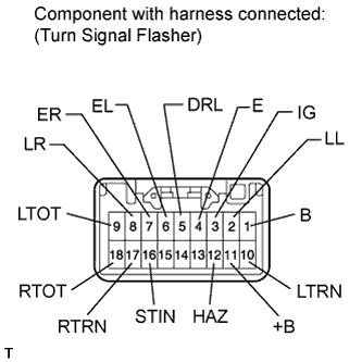
Tester Connection
| Switch Condition
| Specified Condition
|
1 (B) - 4 (E)
| Always
| 11 to 14 V
|
2 (LL) - 4 (E)
| Hazard warning switch OFF
| Below 1 V
|
Hazard warning switch ON
| 9 V or higher (60 to 120 times per minute)
|
3 (IG) - 4 (E)
| Ignition switch ON
| 11 to 14 V
|
6 (EL) - 4 (E)
| Headlight dimmer switch (TURN L) OFF
| 9 V or higher
|
Headlight dimmer switch (TURN L) ON
| Below 1 V
|
7 (ER) - 4 (E)
| Headlight dimmer switch (TURN R) OFF
| 9 V or higher
|
Headlight dimmer switch (TURN R) ON
| Below 1 V
|
8 (LR) - 4 (E)
| Hazard warning switch OFF
| Below 1 V
|
Hazard warning switch ON
| 9 V or higher (60 to 120 times per minute)
|
11 (+B) - 4 (E)
| Always
| 11 to 14 V
|
12 (HAZ) - 4 (E)
| Hazard warning switch OFF
| 9 V or higher
|
Hazard warning switch ON
| Below 1 V
|