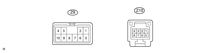
FRONT POWER SEAT CONTROL SYSTEM (w/ Memory) > TERMINALS OF ECU |
| CHECK FRONT POWER SEAT SWITCH LH |
Disconnect the Z9 and Z10 switch connectors.
Measure the voltage and resistance according to the value(s) in the table below.
| Terminal No. (Symbols) | Wiring Color | Terminal Description | Condition | Specified Condition |
| Z9-1 (GND) - Body ground | W-B - Body ground | Ground | Always | Below 1 Ω |
| Z9-5 (+B) - Z9-1 (GND) | L - W-B | Battery (ECU power source) | Always | 11 to 14 V |
| Z10-8 (SYSB) - Z9-1 (GND) | R - W-B | Battery (ECU power source) | Always | 11 to 14 V |
Reconnect the Z9 and Z10 switch connectors.
Measure the voltage according to the value(s) in the table below.
| Terminal No. (Symbols) | Wiring Color | Terminal Description | Condition | Specified Condition |
| Z9-2 (SLD+) - Z9-1 (GND) | P - W-B | Sliding motor signal (forward) | Seat moving forward using sliding switch | 11 to 14 V |
| Other | Below 1 V | |||
| Z9-3 (SLD-) - Z9-1 (GND) | R - W-B | Sliding motor signal (rearward) | Seat moving rearward using sliding switch | 11 to 14 V |
| Other | Below 1 V | |||
| Z9-6 (FRV+) - Z9-1 (GND) | LG - W-B | Front vertical motor signal (upward) | Seat cushion front portion rising using front vertical switch | 11 to 14 V |
| Other | Below 1 V | |||
| Z9-4 (FRV-) - Z9-1 (GND) | W - W-B | Front vertical motor signal (downward) | Seat cushion front portion lowering using front vertical switch | 11 to 14 V |
| Other | Below 1 V | |||
| Z9-8 (RCL+) - Z9-1 (GND) | BE - W-B | Reclining motor signal (forward) | Seatback moving forward using reclining switch | 11 to 14 V |
| Other | Below 1 V | |||
| Z9-10 (RCL-) - Z9-1 (GND) | B - W-B | Reclining motor signal (rearward) | Seatback moving rearward using reclining switch | 11 to 14 V |
| Other | Below 1 V | |||
| Z9-7 (LFT+) - Z9-1 (GND) | G - W-B | Lifter motor signal (upward) | Seat cushion rising using lifter switch | 11 to 14 V |
| Other | Below 1 V | |||
| Z9-9 (LFT-) - Z9-1 (GND) | Y - W-B | Lifter motor signal (downward) | Seat cushion lowering using lifter switch | 11 to 14 V |
| Other | Below 1 V |
| CHECK OUTER MIRROR CONTROL ECU |
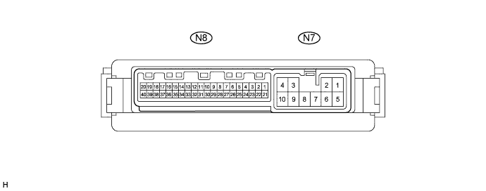
Disconnect the N7 ECU connector.
Measure the voltage and resistance according to the value(s) in the table below.
| Terminal No. (Symbols) | Wiring Color | Terminal Description | Condition | Specified Condition |
| N7-9 (GND) - Body ground | W-B - Body ground | Ground | Always | Below 1 Ω |
| N7-3 (B) - N7-9 (GND) | R - W-B | Battery (ECU power source) | Always | 11 to 14 V |
| N7-4 (ACC) - N7-9 (GND) | Y - W-B | Ignition power supply | Ignition switch OFF | Below 1 V |
| Ignition switch ON | 11 to 14 V |
Reconnect the N7 ECU connector.
Measure the voltage according to the value(s) in the table below.
| Terminal No. (Symbols) | Wiring Color | Terminal Description | Condition | Specified Condition |
| N8-8 (M1) - N8-10 (MSWE) | P - V | Memory 1 switch signal | Memory 1 switch OFF | 11 to 14 V |
| Memory 1 switch ON | Below 1 V | |||
| N8-7 (M2) - N8-10 (MSWE) | BE - V | Memory 2 switch signal | Memory 2 switch OFF | 11 to 14 V |
| Memory 2 switch ON | Below 1 V | |||
| N8-9 (MM) - N8-10 (MSWE) | L - V | Memory SET switch signal | Memory SET switch OFF | 11 to 14 V |
| Memory SET switch ON | Below 1 V |