 |
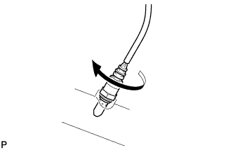
Install the sensor to the exhaust pipe by hand.
AIR FUEL RATIO SENSOR > INSTALLATION |
| 1. INSTALL AIR FUEL RATIO SENSOR (for Bank 2 Sensor 1) |
|
Install the sensor to the exhaust pipe by hand.
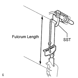 |
Using SST, tighten the sensor.
| 2. INSTALL AIR FUEL RATIO SENSOR (for Bank 1 Sensor 1) |
|
Install the sensor to the exhaust pipe by hand.
|
Using SST, tighten the sensor.
| 3. INSTALL FRONT EXHAUST PIPE ASSEMBLY |
Install a new gasket and the exhaust pipe to the exhaust manifold RH with 3 new nuts.
Install a new gasket and the exhaust pipe to the center exhaust pipe with the 2 bolts.
Connect the air fuel ratio sensor connector.
Connect the heated oxygen sensor connector and 2 clamps.
| 4. INSTALL FRONT NO. 2 EXHAUST PIPE ASSEMBLY (for Regular Cab Standard Deck) |
Install a new gasket and the front No. 2 exhaust pipe to the exhaust manifold LH with 3 new nuts.
Install a new gasket and the front No. 2 exhaust pipe to the front No. 3 exhaust pipe with the 2 bolts and 2 new nuts.
Connect the air fuel ratio sensor connector.
Connect the heated oxygen sensor connector.
| 5. INSTALL FRONT NO. 2 EXHAUST PIPE ASSEMBLY (except Regular Cab Standard Deck) |
Connect the front No. 2 exhaust pipe to the exhaust pipe support.
Install a new gasket and the front No. 2 exhaust pipe to the exhaust manifold LH with 3 new nuts.
Install a new gasket and the front No. 2 exhaust pipe to the center exhaust pipe with the 2 bolts.
Connect the air fuel ratio sensor connector.
Connect the heated oxygen sensor connector.
| 6. INSTALL FRONT PROPELLER SHAFT ASSEMBLY |
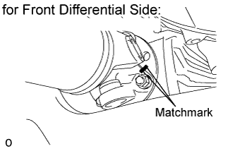 |
for Front Differential Side:
Align the matchmarks on the differential and propeller shaft flange.
Install the propeller shaft with the 4 washers and 4 nuts.
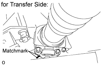 |
for Transfer Side:
Align the matchmarks on the transfer and propeller shaft flange.
Connect the propeller shaft with the 4 washers and 4 nuts.
| 7. INSTALL PROPELLER SHAFT HEAT INSULATOR |
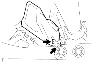 |
Install the heat insulator with the 2 bolts.
| 8. INSPECT FOR EXHAUST GAS LEAK |