Terminal No. (Symbols)
| Wiring Color
| Terminal Description
| Condition
| Specified Condition
|
W2-6 (VV+) - W2-12 (GND)
| BR - W-B
| Display signal (input)
| External device is playing, VTR is displayed
| Pulse generation
|
W2-7 (R1+) - W2-12 (GND)
| G - W-B
| Right channel sound signal (input)
| Disc player is playing
| Waveform synchronized with sound is output
|
W2-8 (L1+) - W2-12 (GND)
| R - W-B
| Left channel sound signal (input)
| Disc player is playing
| Waveform synchronized with sound is output
|
W2-9 (SLD) - W2-12 (GND)*
| Shielded - W-B
| Shielded
| Always
| Below 1 V
|
W2-10 (SGN1) - W2-12 (GND)*
| Y - W-B
| Shielded
| Always
| Below 1 V
|
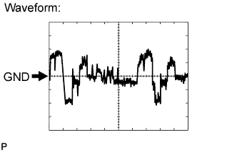
W2-11 (NTSO) - W2-12 (GND)*
| BR - W-B
| Display signal (output)
| DVD displayed on television display
| See waveform
|
W2-13 (TX-) - W2-12 (GND)
| B - W-B
| AVC-LAN communication signal
| Ignition switch ACC
| 2 to 3 V
|
W2-14 (TX+) - W2-12 (GND)
| LG - W-B
| AVC-LAN communication signal
| Ignition switch ACC
| 2 to 3 V
|
W2-22 (VV-) - W2-12 (GND)
| Y - W-B
| Ground
| Always
| Below 1 V
|
W2-23 (SGND) - W2-12 (GND)
| Shielded - W-B
| Shielded
| Always
| Below 1 V
|
W2-24 (ADPG) - W2-12 (GND)
| SB - W-B
| Video terminal ground
| Always
| Below 1 V
|
W2-25 (SGN2) - W2-12 (GND)
| Shielded - W-B
| Shielded
| Always
| Below 1 V
|
W2-26 (MUTE) - W2-12 (GND)
| BE - W-B
| Mute signal
| Television display is playing → Changing modes
| 3.5 V or higher → Below 1 V
|
W2-27 (SLD9) - W2-12 (GND)
| Shielded - W-B
| Shielded
| Always
| Below 1 V
|
W2-28 (R+) - W2-12 (GND)
| B - W-B
| Right channel sound signal (output)
| Disc player is playing
| Waveform synchronized with sound is output
|
W2-29 (R-) - W2-12 (GND)
| G - W-B
| Right channel sound signal (output)
| Disc player is playing
| Waveform synchronized with sound is output
|
W2-30 (L+) - W2-12 (GND)
| R - W-B
| Left channel sound signal (output)
| Disc player is playing
| Waveform synchronized with sound is output
|
W2-31 (L-) - W2-12 (GND)
| W - W-B
| Left channel sound signal (output)
| Disc player is playing
| Waveform synchronized with sound is output
|