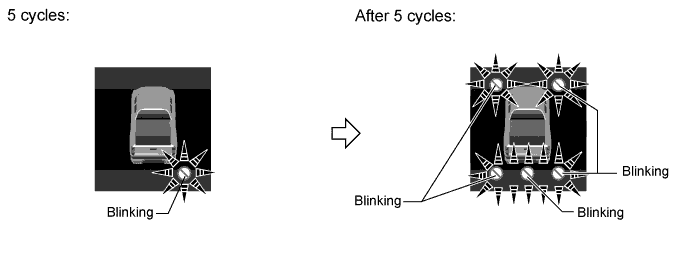
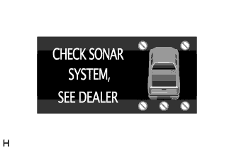
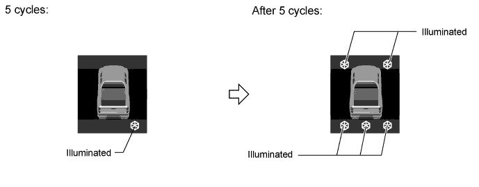
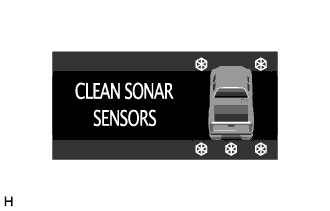
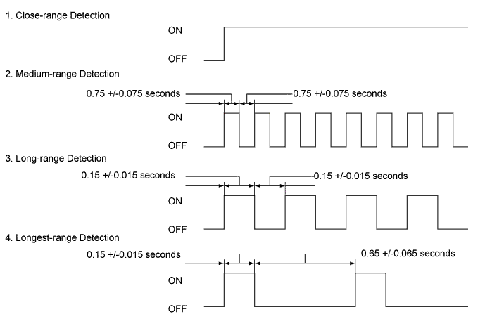
Turn the ignition switch to ON.
Move the shift lever to R to check the front corner sensors, rear corner sensors and back sensors.
Move the shift lever to the D, S and N position to check the front corner sensors.
Turn the back sonar or clearance sonar switch assembly ON.
Move a pole around the sensor to measure the detection range of the sensor.
- NOTICE:
- These detection ranges are applicable when positioning the pole parallel or perpendicular to the ground.
- The ranges vary depending on the measuring method and type of obstacle (such as walls).
- For close-range, medium-range detection and long-range detection, the values shown are for when using a pole with a diameter of 60 mm (2.36 in.). For longest-range detection, the values shown are for when using a pole with a diameter of 400 mm (15.7 in.).
- The detection range of the resin bumper and steel bumper are not the same, as their installation positions are slightly different.
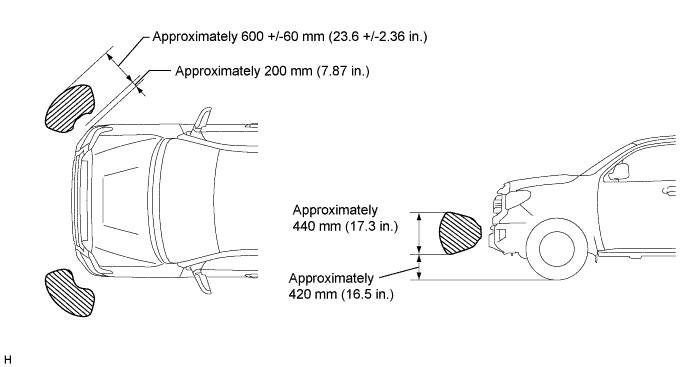
Front corner sensors detection range
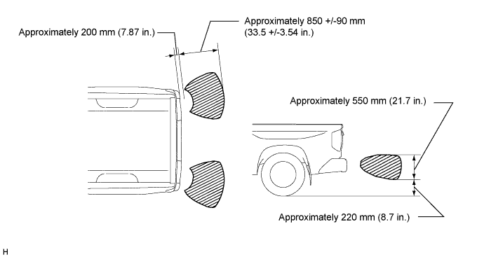
Rear corner sensors detection range
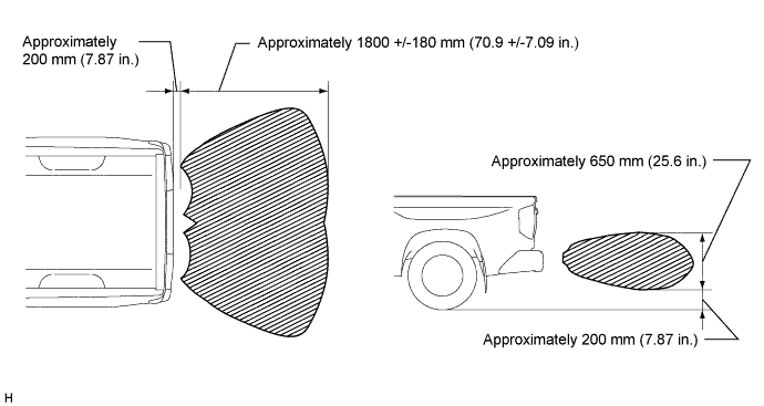
Rear center sensors detection range
When the No. 1 ultrasonic sensors (front corner sensor) have detected an obstacle, check the multi-information display displays and buzzer sounds.
Operation Condition
Ignition Switch
| Back Sonar or Clearance Sonar Switch Assembly
| Shift Lever Position
| Vehicle Speed
|
ON
| ON
| D, S, N, R
| 10 km/h (6.2 mph) or less
|
Check the buzzer sounds with the back sonar or clearance sonar switch assembly ON.
Front corner detection range
Detection
| Distance
|
1. Close-range detection
| Within 300 +/-30 mm (11.8 +/-1.18 in.)
|
2. Medium-range detection
| 300 +/-30 to 450 +/-50 mm (11.8 +/-1.18 to 17.7 +/-1.97 in.)
|
3. Long-range detection
| 450 +/-50 to 600 +/-60 mm (17.7 +/-1.97 to 23.6 +/-2.36 in.)
|
- HINT:
- Ultrasonic waves are used to measure the detection range. However, the detection range may vary depending on the ambient temperature.
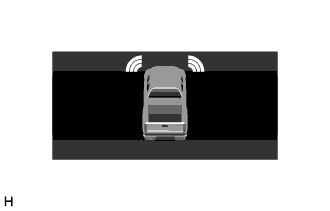
|
Check the indicator and buzzer on the combination meter assembly when the front corner sensors have detected an obstacle.
Combination meter assembly
Detection Range
| Buzzer
| Indicator displayed
|
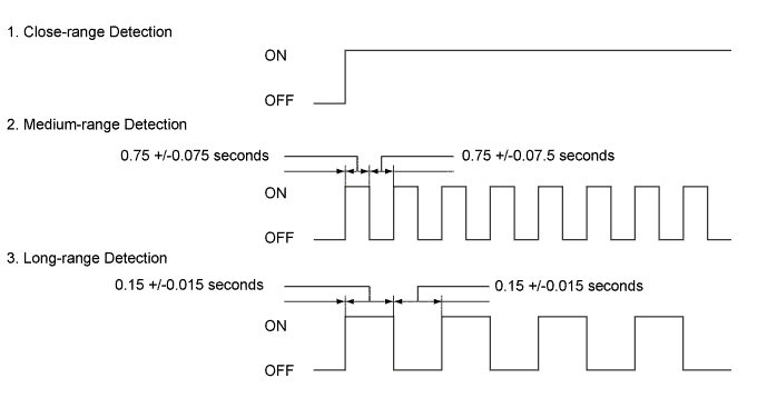
1. Close-range detection
| Sounds continuously
| Corner indicator(s) are blinking
|
2. Medium-range detection
| Sounds intermittently
(ON: 75 msec. / OFF: 75 msec.)
| Corner indicator(s) are illuminated
|
3. Long-range detection
| Sounds intermittently
(ON: 150 msec. / OFF: 150 msec.)
| Corner indicator(s) are illuminated
|
- HINT:
- Ultrasonic waves are used to measure the detection range. However, the detection range may vary depending on the ambient temperature.
When the No. 2 ultrasonic sensors (rear corner sensor) have detected an obstacle, check the multi-information display in the combination meter assembly displays and buzzer in the combination meter assembly sounds with the back sonar or clearance sonar switch assembly ON.
Operation Condition
Ignition Switch
| Back Sonar or Clearance Sonar Switch Assembly
| Shift Lever Position
| Vehicle Speed
|
ON
| ON
| R
| No Limit
|
Check the buzzer sounds with the back sonar or clearance sonar switch assembly ON.
Rear corner detection range
Detection
| Distance
|
1. Close-range detection
| Within 400 +/-40 mm (15.7 +/-1.57 in.)
|
2. Medium-range detection
| 400 +/-40 to 600 +/-60 mm (15.7 +/-1.57 to 23.6 +/-2.36 in.)
|
3. Long-range detection
| 600 +/-60 to 850 +/-90 mm (23.6 +/-2.36 to 33.5 +/-3.54 in.)
|
- HINT:
- Ultrasonic waves are used to measure the detection range. However, the detection range may vary depending on the ambient temperature.
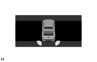
|
Check the combination meter assembly and buzzer when the rear corner sensors have detected an obstacle.
Combination meter assembly
Detection Range
| Buzzer
| Indicator displayed
|
1. Close-range detection
| Sounds continuously
| Corner indicator(s) are blinking
|
2. Medium-range detection
| Sounds intermittently
(ON: 75 msec. / OFF: 75 msec.)
| Corner indicator(s) are illuminated
|
3. Long-range detection
| Sounds intermittently
(ON: 150 msec. / OFF: 150 msec.)
| Corner indicator(s) are illuminated
|
- HINT:
- Ultrasonic waves are used to measure the detection range. However, the detection range may vary depending on the ambient temperature.
When the No. 3 ultrasonic sensors (rear center sensor) have detected an obstacle, check the multi-information display displays and buzzer in the combination meter assembly sounds with the back sonar or clearance sonar switch assembly ON.
Operation Condition
Ignition Switch
| Back Sonar or Clearance Sonar Switch Assembly
| Shift Lever Position
| Vehicle Speed
|
ON
| ON
| R
| No limit
|
Check the buzzer sounds with the back sonar or clearance sonar switch assembly ON.
Rear center detection range
Detection
| Distance
|
1. Close-range detection
| Within 500 +/-50 mm (19.7 +/-1.97 in.)
|
2. Medium-range detection
| 500 +/-50 to 750 +/-80 mm (19.7 +/-1.97 to 29.5 +/-2.95 in.)
|
3. Long-range detection
| 750 +/-80 to 1000 +/-100 mm (29.5 +/-2.95 to 39.4 +/-3.94 in.)
|
4. Longest-range detection
| 1000 +/-100 to 1800 +/-180 mm (39.4 +/-3.94 to 70.9 +/-7.09 in.)
|
- HINT:
- Ultrasonic waves are used to measure the detection range. However, the detection range may vary depending on the ambient temperature.
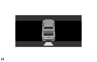
|
Check the combination meter assembly and buzzer when the rear center sensors have detected an obstacle.
Combination meter assembly
Detection Range
| Buzzer
| Indicator displayed
|
1. Close-range detection
| Sounds continuously
| Rear center indicator is blinking
|
2. Medium-range detection
| Sounds intermittently
(ON: 75 msec. / OFF: 75 msec.)
| Rear center indicator is illuminated
|
3. Long-range detection
| Sounds intermittently
(ON: 150 msec. / OFF: 150 msec.)
| Rear center indicator is illuminated
|
- HINT:
- Ultrasonic waves are used to measure the detection range. However, the detection range may vary depending on the ambient temperature.