 |
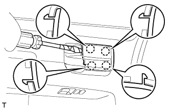
Using a screwdriver, detach the 4 claws and remove the inside handle bezel.
- HINT:
- Tape the screwdriver tip before use.
OUTER REAR VIEW MIRROR > REMOVAL |
| 1. REMOVE FRONT DOOR INSIDE HANDLE BEZEL PLUG |
|
Using a screwdriver, detach the 4 claws and remove the inside handle bezel.
| 2. REMOVE FRONT UPPER ARMREST BASE PANEL LH |
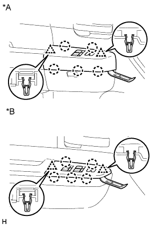 |
Using a moulding remover A, detach the 2 clips and 5 claws, and remove the front upper armrest base panel LH.
| *A | for Regular Cab |
| *B | for Double Cab, for CrewMax |
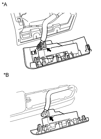 |
Disconnect the master switch connector.
| *A | for Regular Cab |
| *B | for Double Cab, for CrewMax |
| 3. REMOVE FRONT DOOR WINDOW REGULATOR HANDLE ASSEMBLY (w/o Power Window) |
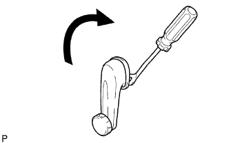 |
Insert a clip remover between the plate and trim.
Turn the handle clockwise to remove the handle.
| 4. REMOVE FRONT LOWER DOOR FRAME BRACKET GARNISH |
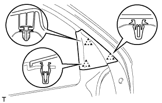 |
Detach the 3 clips and front lower door frame bracket garnish.
| 5. REMOVE FRONT DOOR TRIM BOARD SUB-ASSEMBLY |
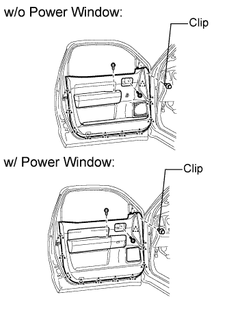 |
Remove the 2 screws.
Using a clip remover, remove the clip.
Detach the 10 clips and remove the trim cover. Then disconnect the connector.
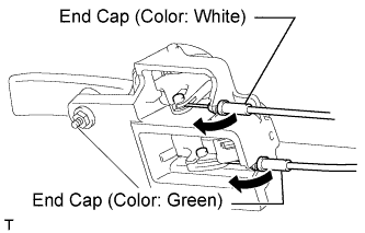 |
Disconnect the 2 cables from the inside handle.
Remove the inside handle.
| 6. REMOVE OUTER REAR VIEW MIRROR ASSEMBLY |
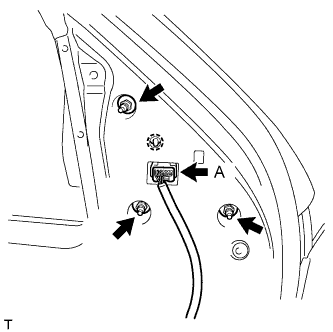 |
w/ Power Mirror Control System:
Disconnect the connector labeled A.
Remove the 3 nuts.
Detach the claw and remove the outer rear view mirror assembly.
| 7. REMOVE OUTER REAR VIEW MIRROR SUB-ASSEMBLY |
Push the upper part of the mirror surface and tilt it.
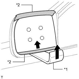 |
Using moulding remover D, push the bottom of the outer rear view mirror sub-assembly LH upwards as shown in the illustration. Slide the outer rear view mirror sub-assembly LH upwards to detach the 4 claws, and then remove the outer rear view mirror sub-assembly LH.
| *1 | Moulding Remover D |
| *2 | Protective Tape |
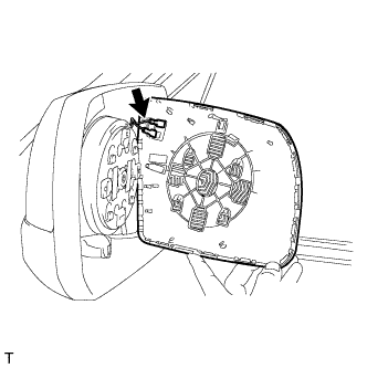 |
w/ Mirror Heater:
Disconnect the 2 connectors and remove the outer rear view mirror sub-assembly LH.
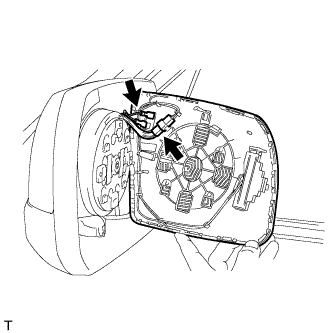 |
w/ Retract Mirror:
Disconnect the 3 connectors and remove the outer rear view mirror sub-assembly LH.
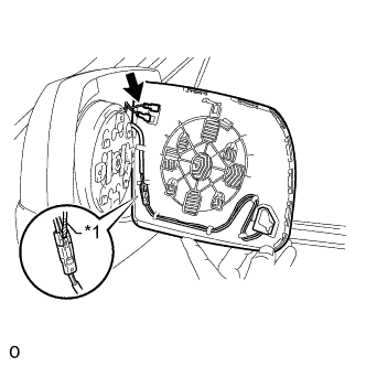 |
w/ Blind Spot Monitor:
Using a screwdriver, disconnect the 3 connectors and remove the outer rear view mirror sub-assembly LH.
| *1 | Protective Tape |
| 8. REMOVE OUTER MIRROR LIGHT ASSEMBLY LH (for Standard) |
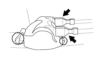 |
Disconnect the 2 connectors.
Detach the 2 claws and remove the outer mirror light assembly LH.
| 9. REMOVE OUTER MIRROR COVER (for Standard) |
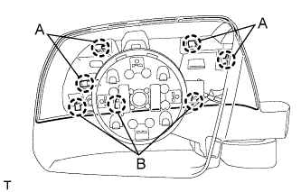 |
Detach the 4 claws labeled A.
Slightly lift up the cover to detach the 3 claws labeled B and remove the outer mirror cover.
| 10. REMOVE SIDE TURN SIGNAL LIGHT LENS (for Extended Type) |
| 11. REMOVE OUTER MIRROR COVER LH (for Extended Type) |
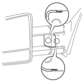 |
Detach the 2 claws and remove the outer mirror cover LH.