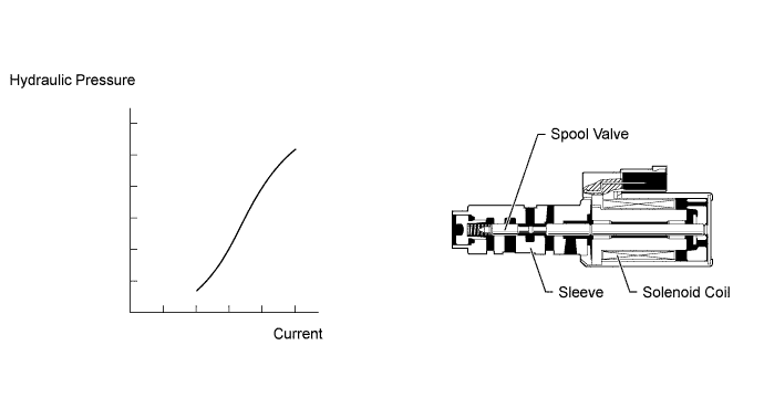
DTC P2757 Torque Converter Clutch Pressure Control Solenoid Performance (Shift Solenoid Valve SLU) |
| DTC Code | DTC Detection Condition | Trouble Area |
| P2757 | Lock-up does not occur when driving in the lock-up range (normal driving at 80 km/h (50 mph)), or lock-up remains ON in the lock-up OFF range (2-trip detection logic). |
|
| Related DTCs | P2757: Shift solenoid valve SLU/Functional check |
| Required sensors/Components | Shift solenoid valve SLU |
| Frequency of operation | Continuous |
| Duration | OFF malfunction (A) 2 seconds OFF malfunction (B) 0.4 seconds ON malfunction 1.8 seconds |
| MIL operation | 2 driving cycles |
| Sequence of operation | None |
| The monitor will run whenever the following DTCs are not present | P0717 (Turbine speed sensor circuit) P0500 (Output speed sensor circuit) P0327, P0328, P0332, P0333 (KCS sensor circuit) |
| Shift solenoid valve S1 circuit | Not circuit malfunction |
| Shift solenoid valve S2 circuit | Not circuit malfunction |
| Shift solenoid valve S3 circuit | Not circuit malfunction |
| Shift solenoid valve S4 circuit | Not circuit malfunction |
| Shift solenoid valve SR circuit | Not circuit malfunction |
| Shift solenoid valve SLU circuit | Not circuit malfunction |
| Shift solenoid valve S1 circuit | Not off malfunction |
| Shift solenoid valve S3 circuit | Not on malfunction |
| Shift solenoid valve S4 circuit | Not off malfunction |
| Shift solenoid valve SL2 circuit | Not on malfunction |
| 1 - 2 shift valve | No malfunction |
| Sequence valve | No malfunction |
| ETCS (Electric Throttle Control System) | Not system down |
| Transmission position | "D" |
| Duration time from shifting "N" to "D" | 4 seconds or more |
| ECT | 40°C (104°F) or more |
| Spark advance from max. retard timing by KCS control | 0° crankshaft angle or more |
| Engine | Starting |
| ECM selected gear | 2nd, 3rd, 4th, 5th or 6th |
| Vehicle speed | 25 km/h (15.5 mph) or more |
| Transfer position | HIGH* |
| Vehicle speed sensor "A" circuit | Not circuit malfunction |
| Output shaft speed sensor circuit | Not circuit malfunction |
| Transfer output speed | 143 rpm or more |
| Transfer input speed / Transfer output speed (NO / NOtf) | 0.9 or more, and less than 1.1 |
| ECM lock-up command | ON (SLU pressure: 513 kPa (5.2 kgf/cm2, 74 psi) or more) |
| Duration time from lock-up on command | 3 seconds or more |
| Vehicle speed | Less than 120 km/h (74.6 mph) |
| ECM selected gear | 2nd |
| Vehicle speed | 2 km/h (1.2 mph) or more |
| Output speed | 2nd → 1st down-shift point or more |
| Throttle valve opening angle | 6.6% or more at 2000 rpm (Conditions vary with engine speed) |
| ECM lock-up command | OFF (SLU pressure: Less than 4 kPa (0.04 kgf/cm2, 0.6 psi)) |
| Duration time from lock-up off command | 3 seconds or more |
| Throttle valve opening angle | 6% or more |
| Vehicle speed | Less than 120 km/h (74.6 mph) in 2nd gear (Varies with ECM selected gear) |
| Engine speed - Turbine speed (NE - NT) | 70 rpm or more |
| Turbine speed / Output speed (NT / NO) | Less than 3.30 or more than 7.50 |
| Engine speed - Turbine speed (NE - NT) | Less than 35 rpm |
| Speed sensor (NT) | Input speed is equal to engine speed when lock-up ON. |
| ACTIVE TEST |
Warm up the engine.
Turn the ignition switch off.
Connect the Techstream to the DLC3.
Turn the ignition switch to ON.
Turn the Techstream on.
Enter the following menus: Powertrain / Engine and ECT / Active Test.
According to the display on the Techstream, perform the Active Test.
| Tester Display | Test Part | Control Range | Diagnostic Note |
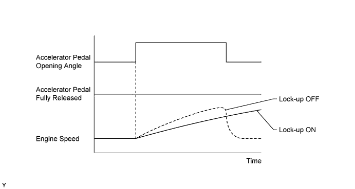
| Activate the Lock Up | Control shift solenoid SLU to set automatic transmission to lock-up | ON or OFF | Possible to check shift solenoid valve SLU operation. [Vehicle Condition]
|
Lightly depress the accelerator pedal and check that the engine speed does not change abruptly.
| 1.CHECK DTC OUTPUT (IN ADDITION TO DTC P2757) |
Connect the Techstream to the DLC3.
Turn the ignition switch to ON.
Turn the Techstream on.
Enter the following menus: Powertrain / Engine and ECT / Trouble Codes.
Read the DTCs using the Techstream.
| Result | Proceed to |
| Only P2757 is output | A |
| P2757 and other DTCs are output | B |
|
| ||||
| A | |
 |
| 2.INSPECT SHIFT SOLENOID VALVE SLU |
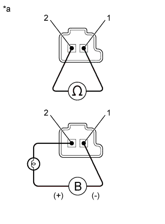 |
Remove shift solenoid valve SLU.
Measure the resistance according to the value(s) in the table below.
| Tester Connection | Condition | Specified Condition |
| 1 - 2 | 20°C (68°F) | 5.0 to 5.6 Ω |
Apply 12 V battery voltage to the shift solenoid valve and check that the valve moves and makes an operating noise.
| Measurement Condition | Specified Condition |
| Valve moves and makes an operating noise |
| *a | Component without harness connected (Shift Solenoid Valve SLU) |
|
| ||||
| OK | |
|
| 3.INSPECT TRANSMISSION VALVE BODY ASSEMBLY |
Check the transmission valve body assembly.
|
| ||||
| OK | |
|
| 4.INSPECT TORQUE CONVERTER ASSEMBLY |
Check the torque converter assembly (Click here).
|
| ||||
| OK | ||
 | ||
| ||
